Coordinated multipoint transmission/reception user grouping

A multi-user and transmitter technology, applied in access restriction, broadcast service distribution, network data management, etc., can solve problems such as low efficiency of RRM scheme and infeasibility of signal processing scheme

Inactive Publication Date: 2011-08-24
TELEFON AB LM ERICSSON (PUBL)
View PDF2 Cites 6 Cited by
  • Summary
  • Abstract
  • Description
  • Claims
  • Application Information

AI Technical Summary

Problems solved by technology

RRM schemes are inefficient, while full knowledge of CSI makes signal processing schemes infeasible

Method used


Image

  • Coordinated multipoint transmission/reception user grouping
  • Coordinated multipoint transmission/reception user grouping
  • Coordinated multipoint transmission/reception user grouping

Examples


Embodiment Construction

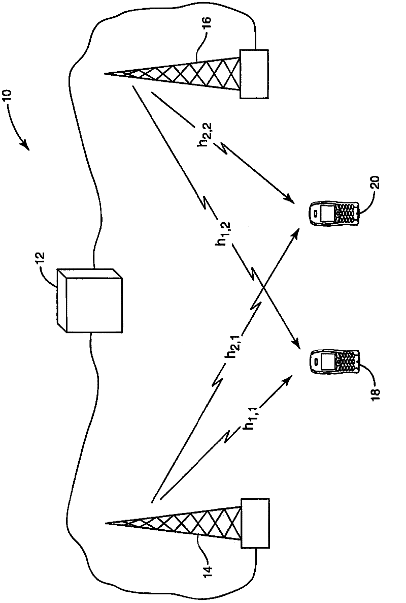
[0015] figure 1 A functional block diagram of an exemplary COMP wireless communication network 10 is shown. The controller 12 weights the signals transmitted by each of the at least two geographically dispersed transmit antennas 14 , 16 . Signals from each antenna 14, 16 are received by each of at least two user equipments (UEs) 18, 20 in an area or cell of operation. Since both transmit antennas 14, 16 and UEs 18, 20 are geographically dispersed, typically each UE 18, 20 will not receive a signal from each transmit antenna 14, 16 with the same signal strength. Conversely, due to path loss, the signals transmitted by the closer antennas 14, 16 will be received with high strength and the signals transmitted by the more distant antennas 14, 16 will be received with weak strength.

[0016] Cross-interference is defined for a UE 18, 20 as the squared ratio of the channel variance of the interfering (ie further) antenna to the channel variance of the desired (ie closer) antenna. ...


PUM


Abstract

User grouping is employed to tradeoff the COMP forward link capacity and required reverse link feedback, which makes the design of COMP practical and flexible. A channel element, such as the large scale fading, is measured for each distributed transmitter (14, 16) and UE (18, 20) pair based on reference signals, and the network (10) receives this information as feedback in the reverse link. The COMP determines a maximum cross interference level areq that is affordable, based on the available reverse link capacity for feedback. If this maximum cross interference level areq is exceeded, geographically separate UEs (18, 20) are divided into as few groups as possible, with UEs (18, 20) within each group separated, and the groups are allocated different time/frequency resource blocks. The grouping is done with the constraint that the cross interference does not exceed areq.

Description

technical field [0001] The present invention relates generally to wireless communication networks, and in particular to a method of grouping user equipment (UE) to improve performance in a coordinated multipoint transmission / reception (COMP) network. Background technique [0002] Such as A.A.M.Saleh, A.J.Rustako Jr. and R.S.Roman in the paper entitled "Distributed antennas for indoor radio communications" (published in IEEE Transactions on Communications, vol.35, no.12, pp.1245-1251, 1987) As mentioned, the predecessor to Coordinated Multipoint Transmission / Reception (COMP), subsequently called Distributed Antenna System (DAS), was originally introduced for coverage improvement in indoor wireless communications. Their scheme involves the discrete realization of delivery to individual users through leaky feeders. In contrast, the concept of COMP enables the transmission of multiple data streams through an interconnected network of radio heads (or base stations), where differ...

Claims


Application Information

Patent Timeline
Patent Type & Authority Applications(China)
IPC IPC(8): H04W72/08
CPCH04W4/08H04W8/24H04W48/08H04W72/082H04W72/0446H04W72/0453H04W72/06H04W72/563H04W72/541
Inventor P·拉森繆庆育甘剑松
Owner TELEFON AB LM ERICSSON (PUBL)
Why Eureka
Try Eureka