New-type binding machine

A binding machine and a new type of technology, applied in binding, metal processing and other directions, can solve the problems of unreasonable, increased cost, complex transmission structure, etc., and achieve the effect of good linkage effect, stable connection and reasonable transmission.

Active Publication Date: 2011-08-31
DELI GROUP CO LTD
View PDF3 Cites 7 Cited by
  • Summary
  • Abstract
  • Description
  • Claims
  • Application Information

AI Technical Summary

Problems solved by technology

[0002] The transmission structure of the tube cutting mechanism of the traditional binding machine is relatively complicated and the transmission structure is unreasonable, which is easy to cause damage, tube cutting failure or inaccurate measuring tube during use
If a pull-wire linkage structure is used, this structure uses a pull wire to measure the length of the pipe that is suitable for the height of the drilled hole and then cut the pipe. It is easy to cause defects such as damage, failure of the cut pipe, or inaccurate measurement of the pipe.
Moreover, the drilling and chip removal structure of the traditional binding machine is relatively complicated and unreasonable, and it is easy to cause blockage and damage during use.
If a straight-through chip removal pipe structure is used, this structure is provided with a straight chip removal channel in the radial direction of the motor shaft and the drill bit, and a paper dust collection box is set on the face of the motor. Because the chip removal channel of this structure is too long It is easy to block, and it is necessary to increase the diameter of the motor rotor shaft and process the inner hollow electronic rotor shaft to increase the cost and cause power loss to the operation of the motor.

Method used


Image

  • New-type binding machine
  • New-type binding machine
  • New-type binding machine

Examples


Embodiment Construction

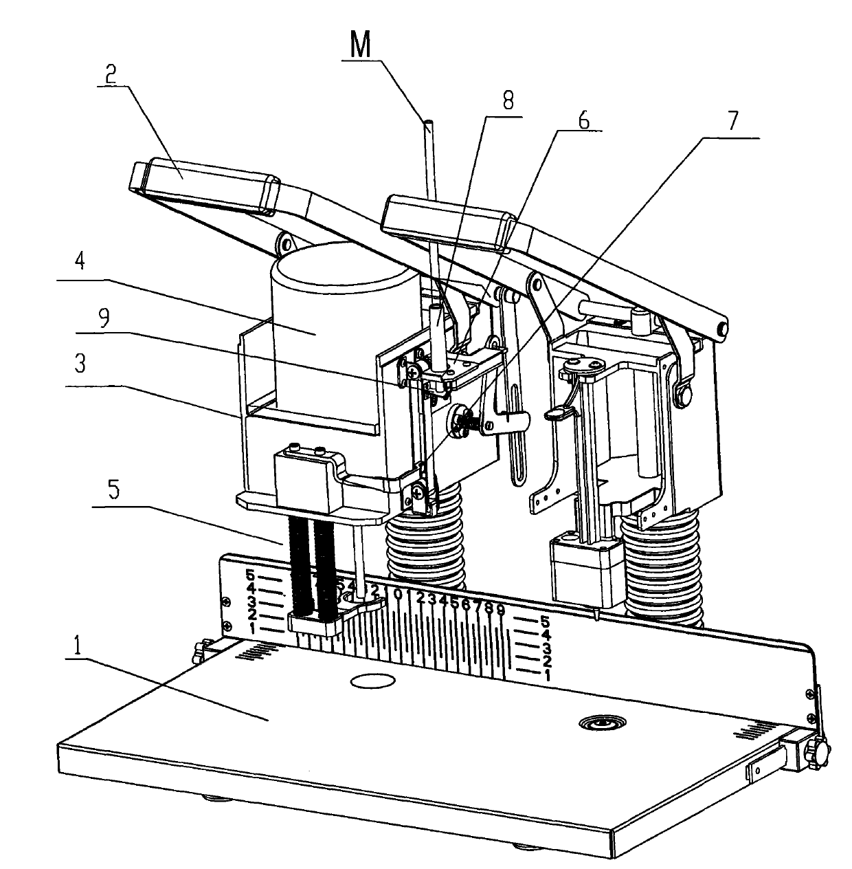
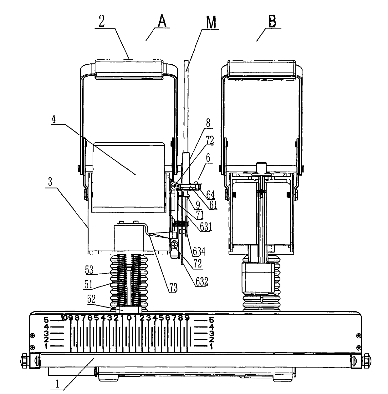
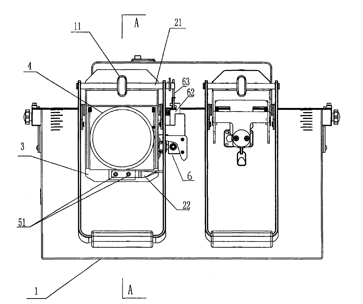
[0034] Such as Figure 1 to Figure 12 As shown, a novel binding machine of the present invention includes a drilling motor 4, a paper pressing device 5, a pipe cutting device 6 and a conduit tube 8 arranged on a liftable motor base 3, and the paper pressing device 5 is positioned on the motor base 3 It can be reset and lifted, and also includes the base 1, the manual pressing rod 2 and the main shaft 11 on the base 1. The motor base 3 is arranged on the main shaft 11, which can be lifted and reset automatically. , between the outer part and the motor seat 3, there is a hinged link piece 22 for interlocking, and the free outer end is a handle; the pipe cutting device 6 is vertically opposite to the catheter tube 8; Guiding and lifting guide device 7, the guide device 7 is provided with a measuring tube supporting plate 9 opposite to the nozzle of the catheter tube 8;

[0035] Such as Figure 9 , Figure 10 As shown, the guiding device 7 includes a synchronous belt 71 and an ...


PUM


Abstract

The invention relates to a new-type binding machine, comprising a drilling motor which can be arranged on an elevated motor base, a paper pressing device, a tube-cutting device and a conduit barrel, wherein the paper pressing device is positioned on the motor base and can be reset and elevated; the tube-cutting device is vertically opposite to the conduit barrel; and the new-type binding machine also comprises a delivery guide device with reverse guiding elevation with the paper pressing device; and the delivery guide device is provided with a measuring tube supporting plate opposite to the pipe orifice of the conduit barrel. The new-type binding machine provided by the invention has the advantages of simple structure, reasonable transmission, stable connection, good linkage effect and the like.

Description

technical field [0001] The invention relates to a binding machine, in particular to a novel binding machine with a drilling and interlocking tube cutting mechanism. Background technique [0002] The transmission structure of the tube cutting mechanism of the traditional binding machine is relatively complicated and the transmission structure is unreasonable, and it is easy to cause damage, tube cutting failure or inaccurate measuring tube during use. If a pull-wire interlocking structure is used, this structure uses a pull wire to measure the length of the pipe that is suitable for the height of the drilled hole and then cut the pipe. When it is used, it is easy to cause defects such as damage, failure to cut the pipe, or inaccurate measuring pipe. Moreover, the drilling and chip removal structure of the traditional binding machine is relatively complicated and unreasonable, and it is easy to cause blockage and damage during use. If a straight-through chip removal pipe stru...

Claims


Application Information

Patent Timeline
Patent Type & Authority Applications(China)
IPC IPC(8): B42B5/00B26F1/16B26D1/06
Inventor 孙兵
Owner DELI GROUP CO LTD
Why Eureka
Try Eureka