
Electrified railway in-phase power supply device and multi-target coordinated instantaneous current control method

A technology for electrified railways and in-phase power supply, which is applied in the direction of power lines, transportation and packaging, and conversion equipment for intermediate conversion to DC, which can solve the problems of few control targets and inability to apply in-phase power supply devices, etc., to improve voltage transients Stability, improvement of power quality, effect of reducing quantity

Inactive Publication Date: 2011-08-31
XUJI GRP +2
View PDF3 Cites 25 Cited by
  • Summary
  • Abstract
  • Description
  • Claims
  • Application Information

AI Technical Summary

Problems solved by technology

[0007] The purpose of the present invention is to provide a multi-objective coordinated instantaneous current control method for in-phase power supply devices of electrified railways to solve the problem that the existing traction converter control methods have relatively few control targets, relatively simple control strategies, and cannot be applied to in-phase power supply devices problem, and provides a same-phase power supply device for electrified railways using the method

Method used


Image

  • Electrified railway in-phase power supply device and multi-target coordinated instantaneous current control method
  • Electrified railway in-phase power supply device and multi-target coordinated instantaneous current control method
  • Electrified railway in-phase power supply device and multi-target coordinated instantaneous current control method

Examples


Embodiment Construction

[0019] The present invention will be further introduced below in combination with specific embodiments.

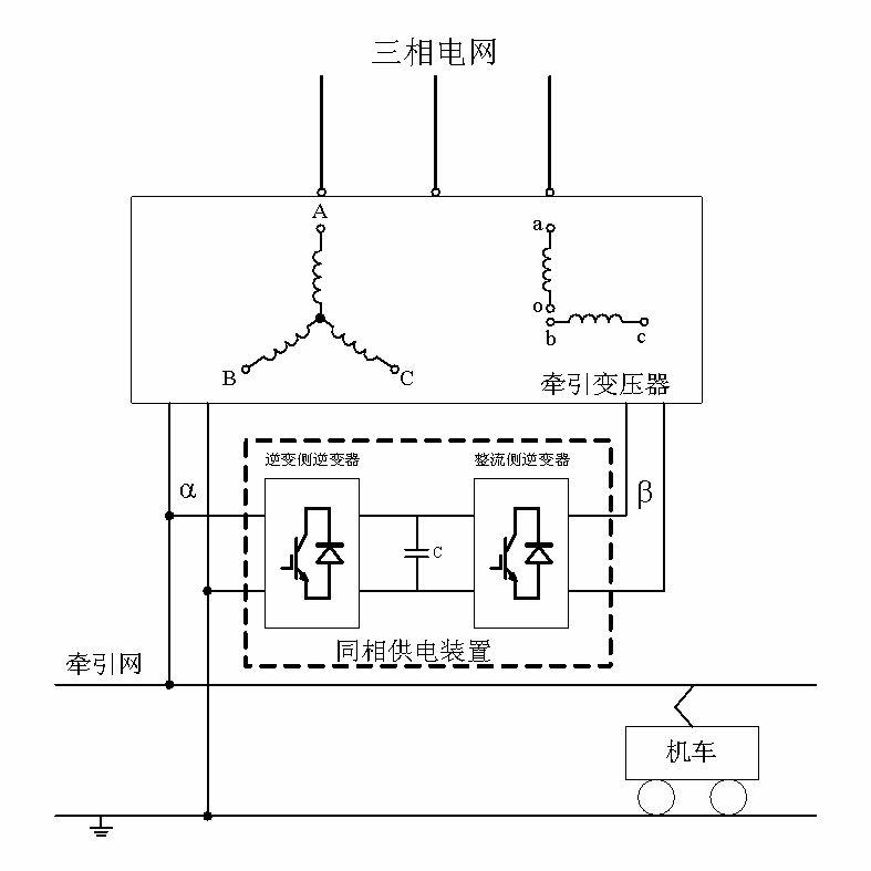
[0020] Such as figure 1 As shown, the electrified railway in-phase power supply device of the present application is installed at the two ports of the traction transformer, and the railway traction network cancels the electric phase separation link, and uses the α-phase power supply provided by the traction transformer. The same-phase power supply device consists of single-phase back-to-back AC-DC-AC inverters, including rectification-side inverters, DC-side support capacitors and inverter-side inverters. The rectification-side inverters are connected to the β port of the traction transformer, and the inverter-side inverters The capacitor is connected to the α port of the traction transformer, and the supporting capacitor on the DC side is connected between the inverter on the rectification side and the inverter on the inverter side.

[0021] When the traction load is in ...


PUM


Abstract

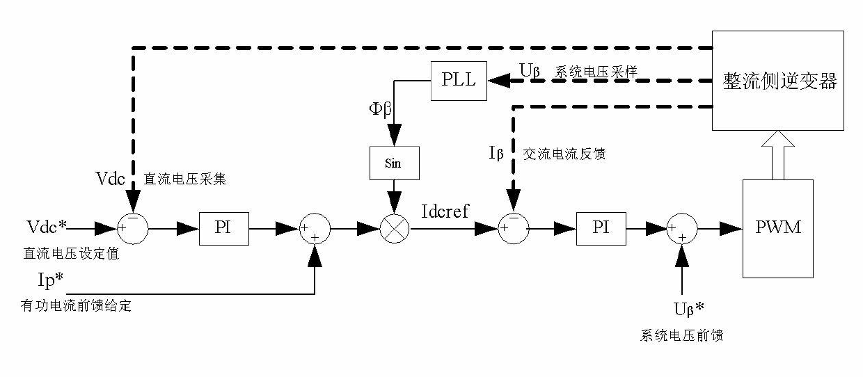
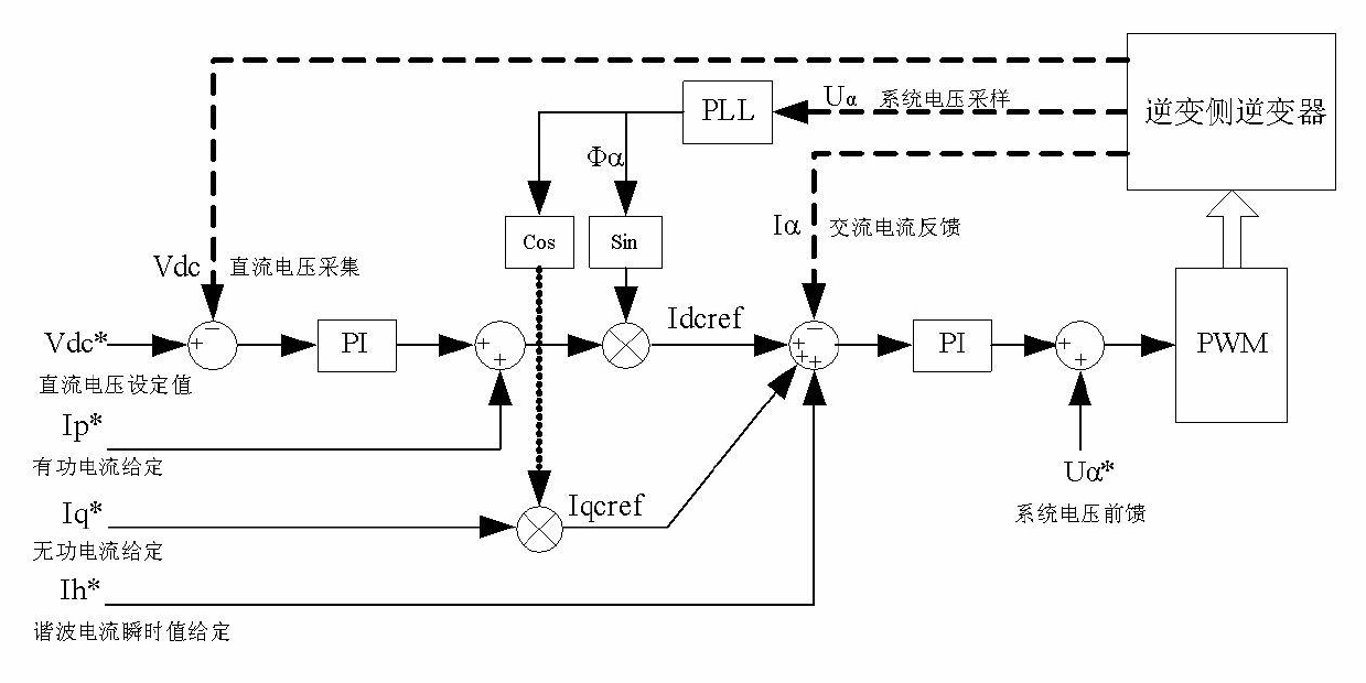
The invention relates to an electrified railway in-phase power supply device and a multi-target coordinated instantaneous current control method adopted by the device. After the in-phase power supply device is used, the electrified railway whole-line in-phase power supply can be realized, the output power of two power supply arms of a traction transformer can be balanced, and the negative sequence problem can be thoroughly solved; the load reactive power and the harmonic current can be compensated, and the electric energy quality of a traction power supply system can be comprehensively improved; the voltage of a traction electric network can be stabilized, the transient state stability of the voltage can be improved, the power supply distance of the power supply arms can be increased, and the amount of power substations can be reduced; the electrified railway in-phase power supply device and the multi-target coordinated instantaneous current control method are multiple in targets, the multi-target can be simultaneously controlled, the control harmony at two sides can be guaranteed, the dynamic response capability is stronger; a rectification side inverter takes the active power transfer and the stable direct voltage as a control target, and participates the reactive power control; and an inversion side inverter performs active power, reactive power and harmonic wave control, and participates the stable control of the direct voltage.

Description

technical field [0001] The invention relates to an electrified railway in-phase power supply device and a multi-objective coordinated instantaneous current control method adopted. Background technique [0002] At present, my country's traction power supply system adopts a different-phase (two-phase) unilateral power supply mode. The unilateral power supply mode and the existing traction substation wiring mode and its commutation connection determine that there must be an electrical phase separation link on the traction network. When the automatic phase separation device on the ground fails, the train will break through the phase separation link; while the automatic phase separation device on the train fails, it will affect the operation of the locomotive. The electric phase separation link has a great restrictive effect on high-speed and heavy-duty traffic. At the same time, problems such as negative sequence and harmonics will become more serious under high-speed and heavy ...

Claims


Application Information

Patent Timeline
Patent Type & Authority Applications(China)
IPC IPC(8): B60M3/00H02M5/42
Inventor 张建兴王定国陈天锦张东江曹智慧仇志凌陈世峰王涛李正力于文杰张一平
Owner XUJI GRP
Learn More