Experiment method for pulsed laser single event upset cross section

A single-particle flip, pulsed laser technology, used in electronic circuit testing, measuring devices, instruments, etc.

Inactive Publication Date: 2011-08-31
NO 510 INST THE FIFTH RES INST OFCHINA AEROSPAE SCI & TECH
View PDF3 Cites 31 Cited by
  • Summary
  • Abstract
  • Description
  • Claims
  • Application Information

AI Technical Summary

Problems solved by technology

[0004] The purpose of the present invention is to solve the problem of obtaining the laser flip section curve on the pulse laser single event effect system in the laboratory, and propos...

Method used


Image

  • Experiment method for pulsed laser single event upset cross section
  • Experiment method for pulsed laser single event upset cross section
  • Experiment method for pulsed laser single event upset cross section

Examples


Embodiment 1

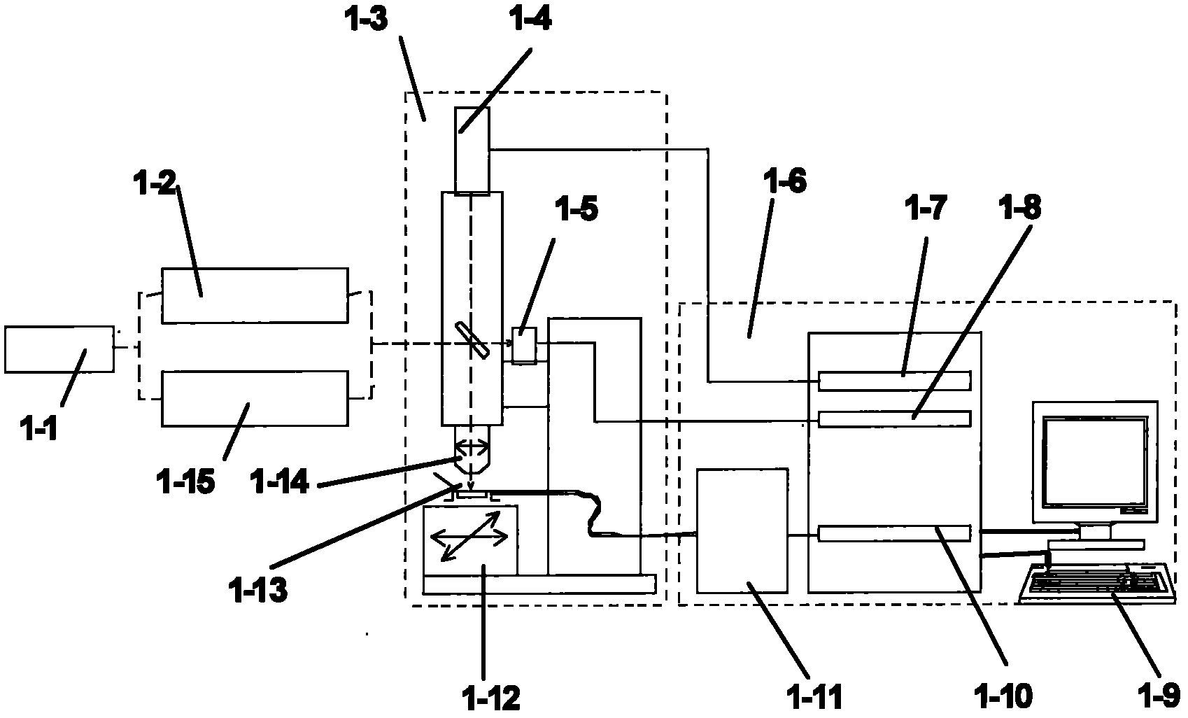
[0036] The pulsed laser simulates the IDT6116 single event effect test, and its experimental system is as follows: figure 1 shown.

[0037] (1) Uncover the IDT6116 device in the ceramic package, place the normal IDT6116 device on the DUT mobile platform of the laser simulation single event effect test system, and correctly connect the test system and power supply system;

[0038] (2) Focusing and positioning the DUT platform sample of the laser simulation single event effect test system;

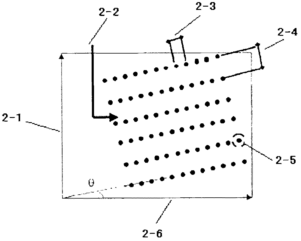
[0039] (3) Determine the coordinates of the irradiation origin (starting point), scanning parameters (x-axis moving speed, y-axis moving speed, time interval between x-axis and y-axis moving, etc.) information and irradiation scanning layout (irradiation times), such as figure 2 shown.

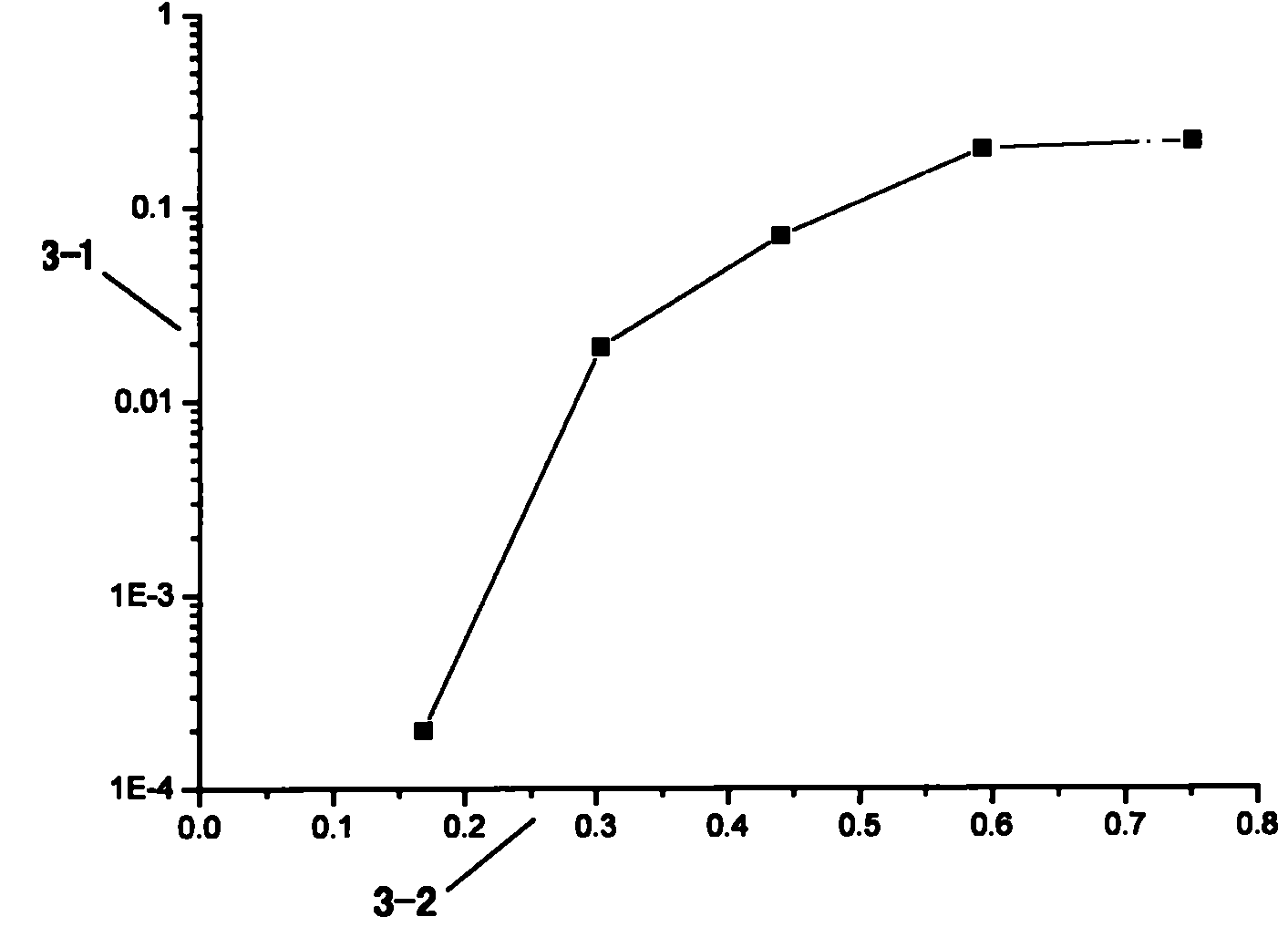
[0040] (4) On the basis that the sample is working normally, select the pulsed laser energy of 0.01-10nJ to start scanning irradiation. During the irradiation process, the monitoring system monitors the ...


PUM


Abstract

The invention provides an experiment method for a pulsed laser single event upset cross section. The method comprises the steps of scanning and irradiating an inside of a device according to pulsed laser E of a certain value; obtaining a laser single event upset cross section value under the E according to single event upset frequency, irradiation frequency (stationing number of scanning) of the monitored device; and obtaining a Sigma~E curve of the laser single event upset cross section through changing the pulsed laser with different energy for scanning and irradiating. The invention provides technical support for pre-estimating single event upset resistance of a to-be-tested device and enables easier and more practical research on ground pulsed laser simulation of single event effects in the future.

Description

technical field [0001] The invention relates to an experimental method for flipping a section of a pulsed laser single particle, which belongs to the technical field of space radiation effect and reinforcement. Background technique [0002] Single Event Upset (SEU) is a phenomenon in which high-energy charged particles in the space radiation environment interact with electronic devices or circuits, causing logic errors and abnormal functions. Due to the use of a large number of microelectronic devices and integrated circuits on the spacecraft, the safe and reliable operation of the spacecraft depends on the normal operation of these devices and circuits, and the spacecraft is flying in space and has always been in a radiation environment composed of charged particles . High-energy particles in the space radiation environment can cause SEU in satellite devices and circuits, which has become the main factor affecting the high reliability and long life of spacecraft in orbit, ...

Claims


Application Information

Patent Timeline
IPC IPC(8): G01J11/00G01R31/00G01R31/311
Inventor 薛玉雄把得东马亚莉安恒杨生胜曹洲田恺
Owner NO 510 INST THE FIFTH RES INST OFCHINA AEROSPAE SCI & TECH
Why Eureka
Try Eureka