
Spacer dispensing device, spacer dispensing method and producing method of liquid crystal panel

A substrate and platen technology, applied in nonlinear optics, instruments, optics, etc., can solve the problems of easy charging rigidity, the inability of spacers to evenly distribute resin-made substrates, and the difficulty of evenly disposing spacers, etc., and achieve the effect of preventing static electricity.

Inactive Publication Date: 2011-08-31
FUJITSU FRONTECH LTD
View PDF6 Cites 5 Cited by
  • Summary
  • Abstract
  • Description
  • Claims
  • Application Information

AI Technical Summary

Problems solved by technology

However, the existing spacer spraying device is based on the premise of a glass substrate, so if it is directly applied to a resin substrate, there is a problem that it is difficult to spread the spacer uniformly
[0007] For example, in general, resin substrates (especially film substrates) are easier to charge and have lower rigidity than glass substrates. Figure 7 In the example above, there is a problem that friction is easily generated between the resin substrate and the table 90c, and the static electricity generated by the friction makes it difficult to arrange the spacers 91 uniformly.
Therefore, for example, there is a problem that the resin substrate moves in the up-down direction due to the wind pressure of the compressed air released together with the spacer 91.
At this time, the table surface of the lower table 90c is in contact with the resin substrate to cause friction, and frictional static electricity is generated. Due to the influence of this static electricity, the charged spacers may not be evenly spread on the resin substrate.
In addition, when the resin substrate is transported, the same problem occurs because the resin substrate passes above the table 90c.

Method used


Image

  • Spacer dispensing device, spacer dispensing method and producing method of liquid crystal panel
  • Spacer dispensing device, spacer dispensing method and producing method of liquid crystal panel
  • Spacer dispensing device, spacer dispensing method and producing method of liquid crystal panel

Examples


Embodiment Construction

[0033] Hereinafter, embodiments of the present invention will be described with reference to the drawings.

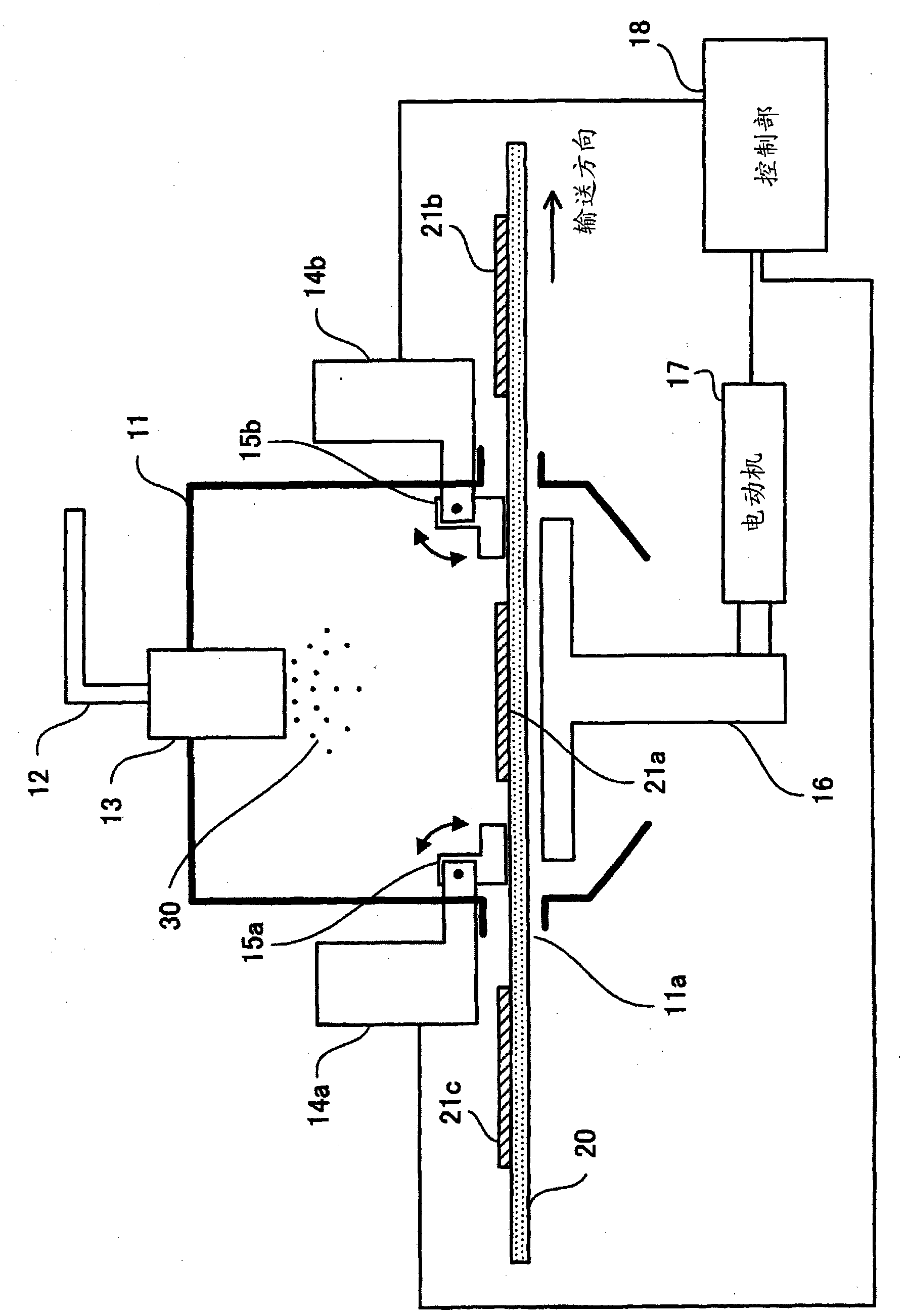
[0034] figure 1 It is a figure which shows the structural example of the spacer spraying apparatus of embodiment.

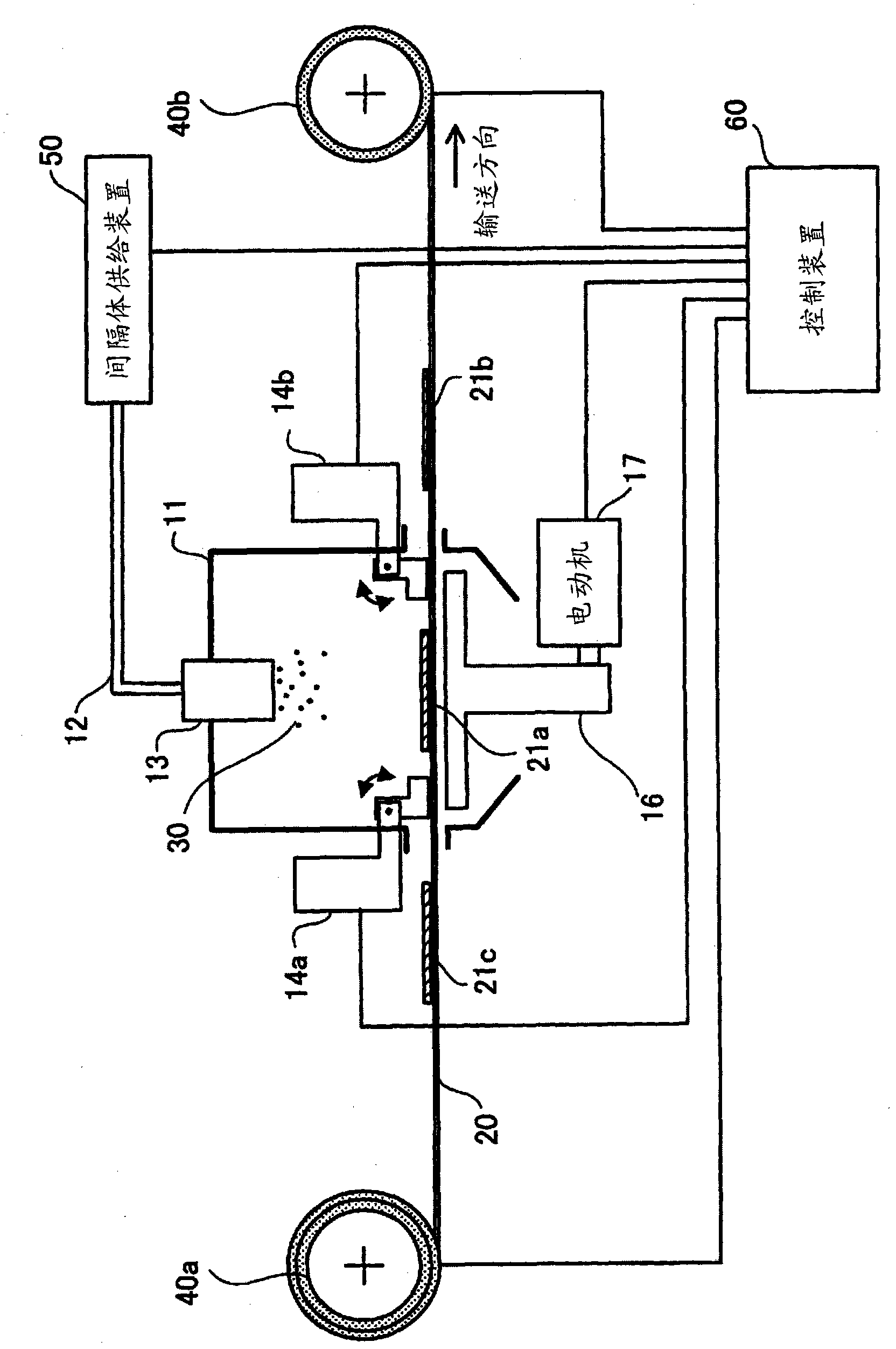
[0035] The spacer spraying device performs a spacer spraying process on a film substrate 20 in which individual electrode patterns are continuously formed on a film-like thin resin substrate. The spacer distributing device has an outer shell container 11, a pipe 12 for conveying the spacer 30 into the container 11, a nozzle 13 for distributing the spacer 30, a platen mechanism part 14a, 14b for pressing the film substrate 20, and an operation for placing the film substrate 20. Table 16, motor 17 for moving table 16, and control unit 18.

[0036] The container 11 is the casing of the spacer spreading device, and can make the inside of the spacer spreading device airtight or close to airtight. An exhaust port 11 a for exhausting the compressed air releas...


PUM


Abstract

Provided is a spacer dispensing device, a spacer dispensing method and a producing method of a liquid crystal panel. The invention aims to evenly place spacers on a resin substrate. As a solution, when conveying a film substrate (20), a control part (18) indicates pressing plate mechanism parts (14a, 14b), enabling pressing plates (15a, 15b) to raise and leave the film substrate (20) to convey the film substrate (20). When reaching to a regulated position and dispensing a spacer (30), a dispensing object electrode pattern (21a) indicates the pressing plate mechanism parts (14a, 14b), making the pressing plates (15a, 15b) decline to be placed on the film substrate (20) to inhibit the movement of the film substrate (20).

Description

technical field [0001] The present invention relates to a spacer spreading device for spreading spacers on an electrode pattern formed on a substrate, a spacer spreading method, and a liquid crystal panel manufacturing method using the spacer spreading device. Background technique [0002] In the manufacture of liquid crystal panels, there is a spacer spraying process in which metal fine particles, synthetic resin fine particles, inorganic fine particles, etc. called spacers are placed on electrode patterns formed on a substrate in order to maintain the space between liquid crystal panels. As one of the spacer spraying methods, there is a spacer spraying method of blowing a spacer onto a substrate together with compressed air. In this spacer spreading process, spacers need to be uniformly arranged on the substrate from the viewpoint of quality, and various methods for uniformly spreading spacers have been proposed. [0003] Figure 7 It is a figure which shows an example of...

Claims


Application Information

Patent Timeline
Patent Type & Authority Applications(China)
IPC IPC(8): G02F1/1339G02F1/1333
Inventor 高梨哲也
Owner FUJITSU FRONTECH LTD
Learn More