Preheating circuit applied to fluorescent lamp electronic ballast
A technology for electronic ballasts and preheating circuits, applied to light sources, electric light sources, electrical components, etc., can solve problems such as reducing the efficiency of ballasts, and achieve the effect of improving efficiency
- Summary
- Abstract
- Description
- Claims
- Application Information
AI Technical Summary
Problems solved by technology
Method used
Image

Examples
Embodiment Construction
[0010] Below in conjunction with accompanying drawing, preferred specific embodiment of the present invention is described:
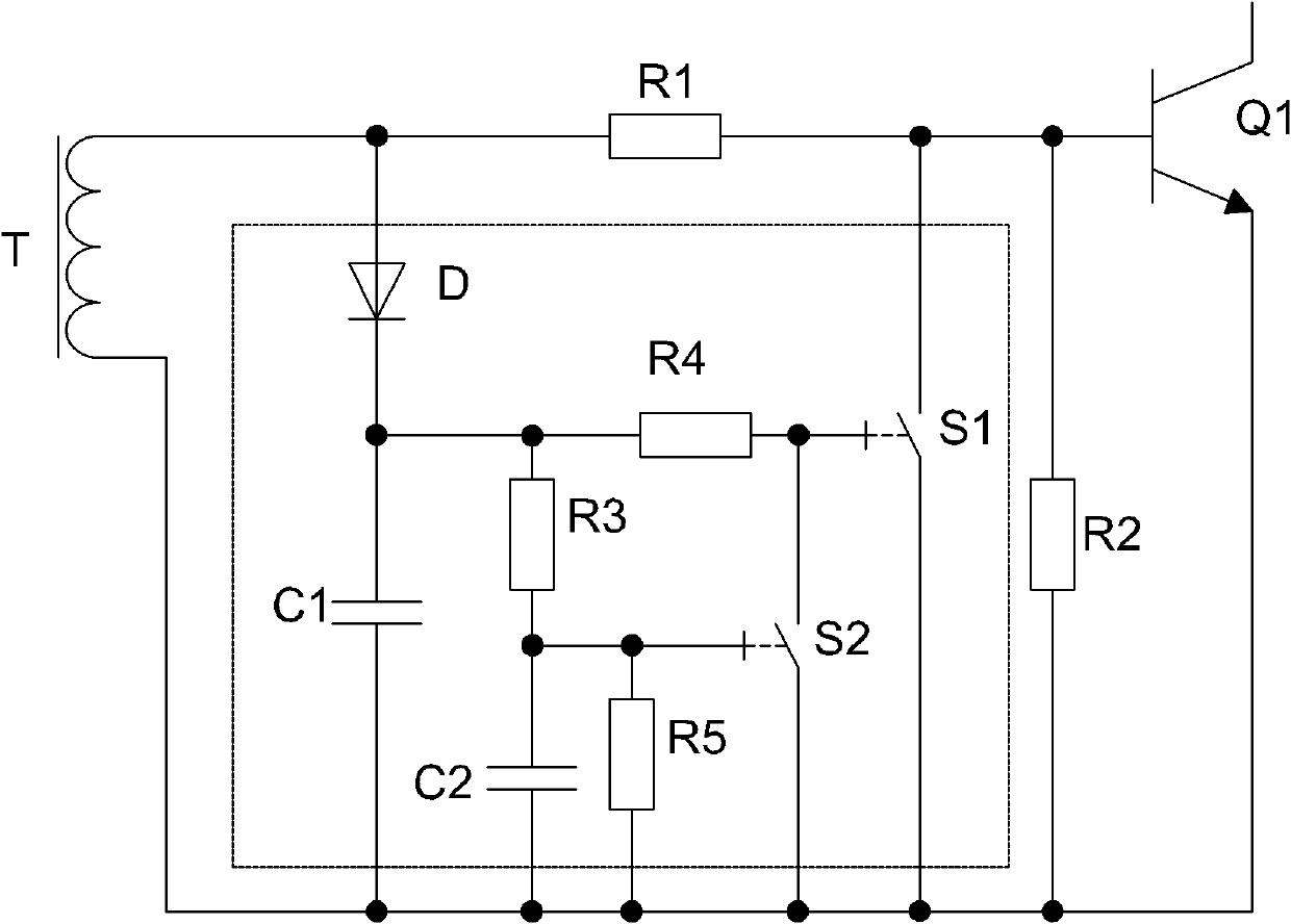
[0011] For example, 1 shows part of the circuit of the electronic ballast, which mainly includes the self-excited ring drive circuit and the preheating circuit. A driving resistor R1 and a second driving resistor R2, a power transistor Q1 whose base is connected between the first driving resistor R1 and the second driving resistor R2, and an emitter of the power transistor Q1 is connected to the other end of the second driving resistor R2.
[0012] The preheating circuit includes a diode D and a first capacitor C1 connected in series to the secondary winding T of the magnetic ring, a third resistor R3 and a second capacitor C2 connected in parallel to the first capacitor C1 in series, and the diode D and the first control switch S1 connected in parallel with the series branch of the first capacitor C1, and the second control switch S2 connected in paral...
PUM
 Abstract
Description
Claims
Application Information
PatSnap Eureka turns technology decisions into work you can execute. Powered by our Innovation Knowledge Graph, it runs expert workflows across engineering, life sciences, materials and intellectual property. Get your review-ready output in minutes.


