Implement having a hybrid drive

A technology of tools and energy storage devices, applied in the direction of power devices, hybrid vehicles, pneumatic power devices, etc., can solve problems such as high fuel consumption and achieve the effect of improving efficiency

Inactive Publication Date: 2011-08-31
WACKER NEUSON SE
View PDF2 Cites 33 Cited by
  • Summary
  • Abstract
  • Description
  • Claims
  • Application Information

AI Technical Summary

Problems solved by technology

resulting in an overall higher fuel consumption

Method used


Image

  • Implement having a hybrid drive
  • Implement having a hybrid drive
  • Implement having a hybrid drive

Examples


Embodiment Construction

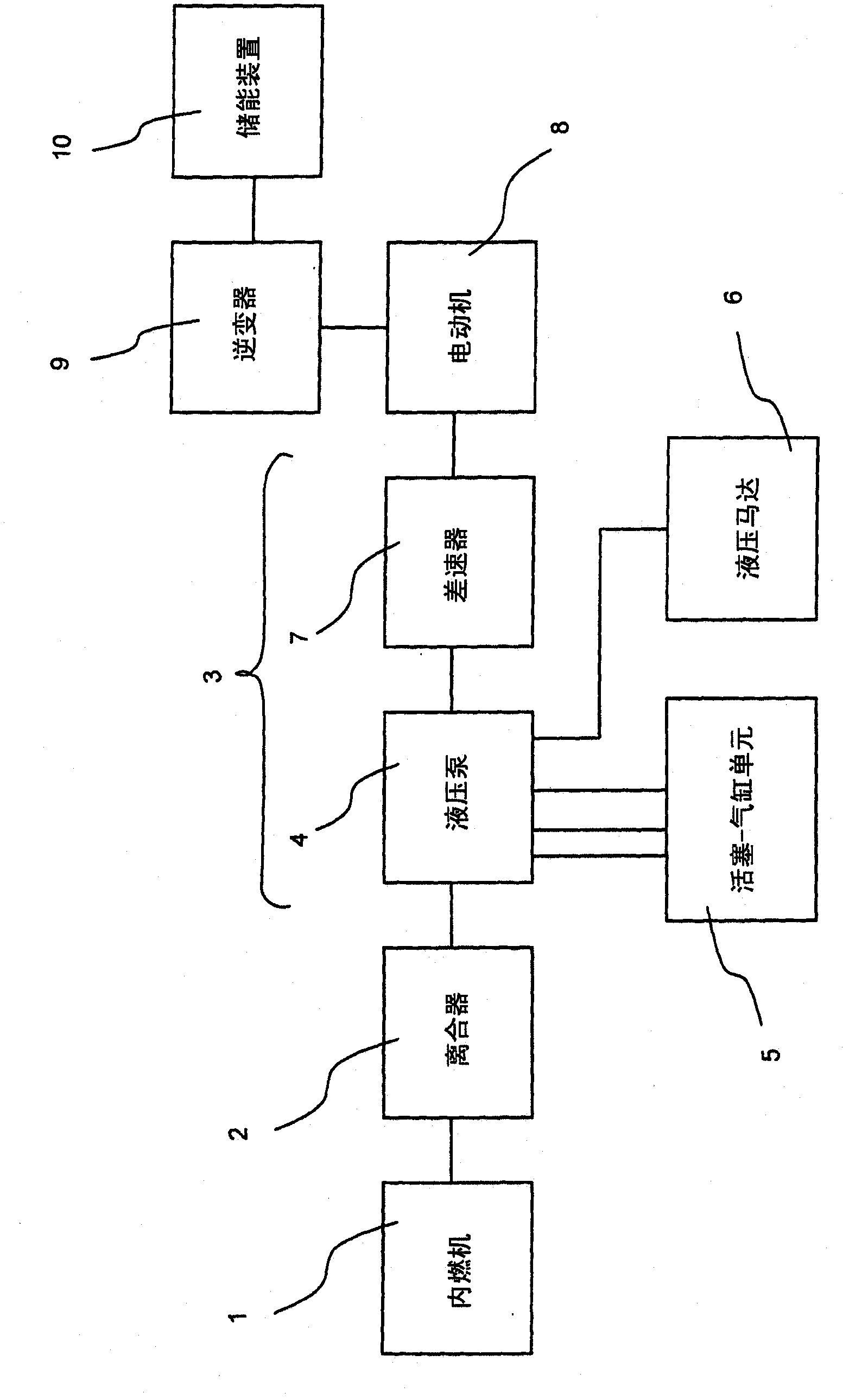
[0060] figure 1 The principle structure of the mixing system of the tool according to the invention is shown schematically.

[0061] The internal combustion engine 1 is coupled via a clutch 2 to a main drive train 3 , which represents the operative coupling. By means of a clutch 2 , which can be controlled via a control device (not shown), the internal combustion engine 1 can be connected to or disconnected from the main drive train 3 as required. This will be further elaborated below.

[0062] In the main drive train 3 there are one or more hydraulic pumps 4 which are driven by the internal combustion engine 1 in normal operation in order to convey and pressurize hydraulic fluid (hydraulic oil) in a known manner in the hydraulic system. The hydraulic pump 4 is correspondingly connected to one or more piston-cylinder units 5 . On its side, the piston-cylinder unit 5 is again used, for example, to raise or lower the arms of an excavator or loader or to move a bucket.

[006...


PUM


Abstract

The invention relates to an implement having an internal combustion engine (1) and a hydraulic system (4, 5, 6) that can be driven by the internal combustion engine (1) for bringing about a working movement. Furthermore, an energy accumulator (10) is provided for the storage of energy in an accumulation phase in which the output delivered by the internal combustion engine (1) is greater than the output currently required by the hydraulic system, and for the delivery of energy in a discharge phase in which the output delivered by the internal combustion engine (1) is smaller than the output currently required by the hydraulic system. The energy accumulator (10) thus serves for balancing output peaks and valleys such that the internal combustion engine (1) may always be operated within an optimum range of rotational speeds.

Description

technical field [0001] The invention relates to a tool with a drive motor and a working mechanism drivable by the drive motor. Background technique [0002] Such implements are in particular mobile implements such as trucks, forklifts, excavators and dumpers. What these tools have in common is that most of them are not very efficient. Generally, a higher engine power must be provided in order to also meet the power requirements of peak loads. The potential energy gained by raising the load will be transferred to the hydraulic system (hydraulic oil) in the form of flow losses when the load is lowered. Therefore, hydraulic cooling must be provided, which is sufficiently dimensioned and is often additionally combined with forced ventilation. This results in an overall higher fuel consumption. Contents of the invention [0003] The object of the present invention is therefore to specify a tool with which a consistently high productivity can be achieved with significantly l...

Claims


Application Information

Patent Timeline
Patent Type & Authority Applications(China)
IPC IPC(8): B60K6/48E02F9/22E02F9/20
CPCB60L11/005B60Y2200/41E02F9/2217Y02T10/7005B60W10/06B60W10/24B60L11/1861B60W10/30B60L2220/18Y02T10/7044Y02T10/7077Y02T10/6286B60K6/105B60L11/14E02F9/2025Y02T10/705Y02T10/6204E02F9/2075Y02T10/6282B60W10/08B60W20/00B60L7/06Y02T10/6221Y02T10/7022B60K6/48B60K2006/4833B60L2200/26B60L50/16B60L50/40Y02T10/62Y02T10/70Y02T10/7072B60W10/26B60W20/13
Inventor O·W·斯坦佐
Owner WACKER NEUSON SE
Why Eureka
Try Eureka