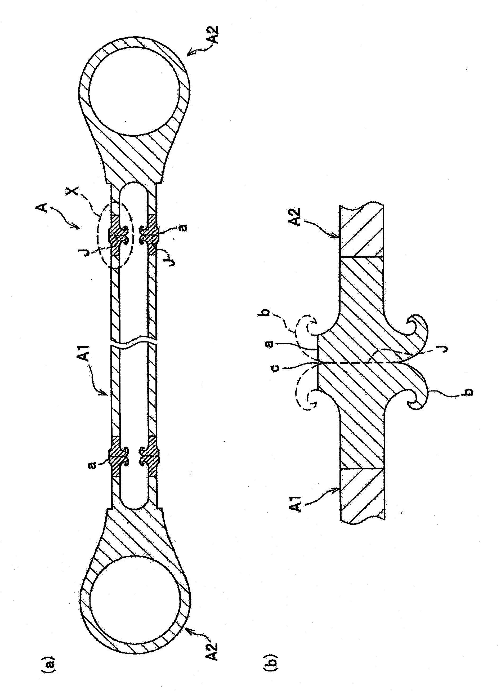
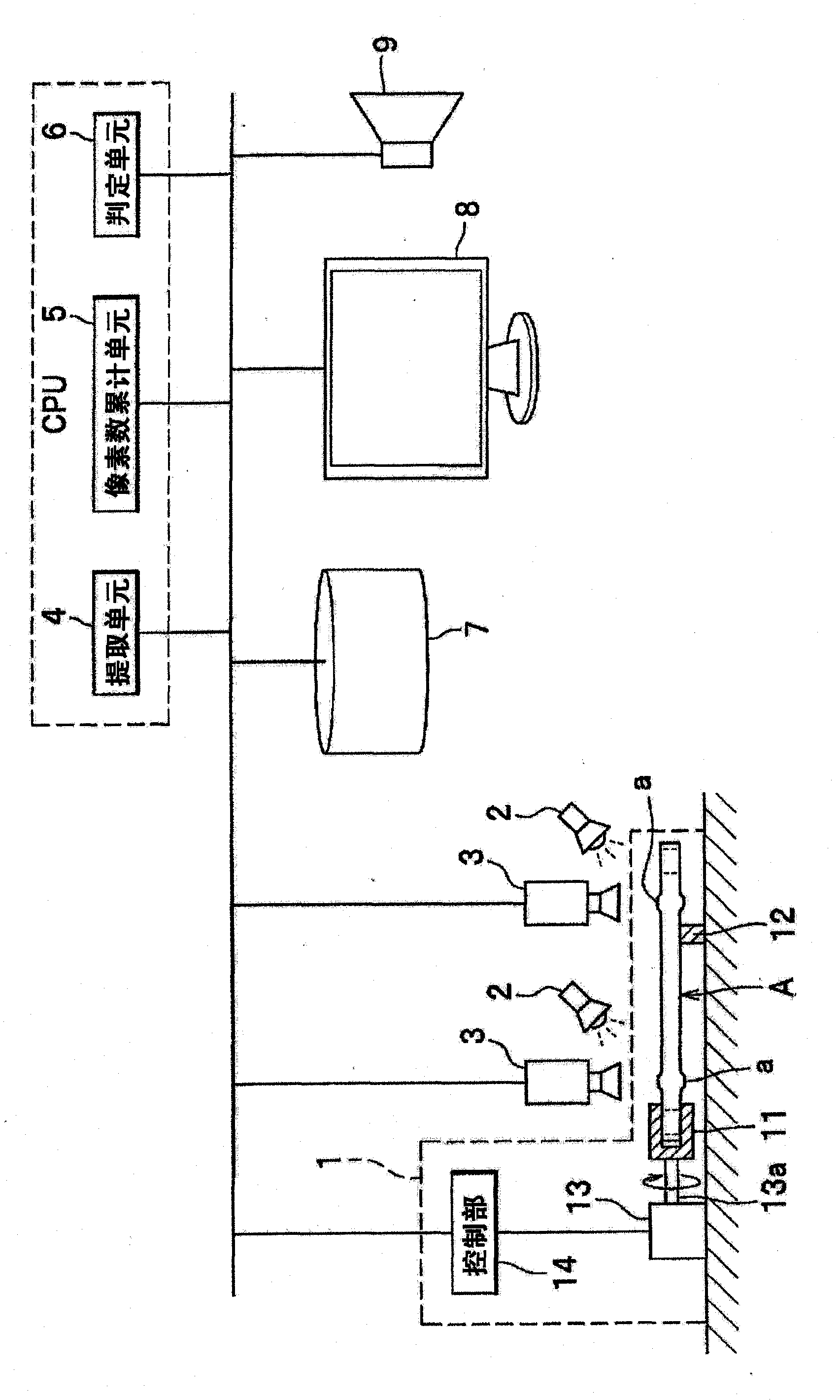
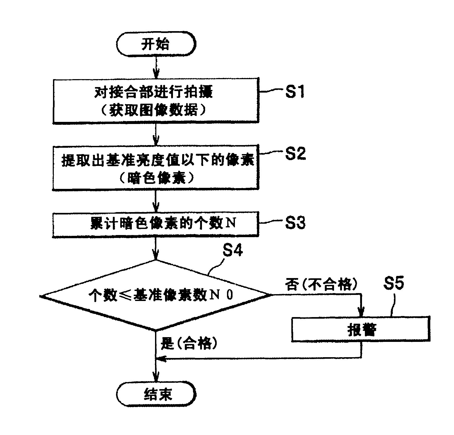
[0037] The joining quality control method according to the present embodiment is performed on a friction welding member obtained by cutting off burrs generated on the outer peripheral side of the joining portion.
[0038] In the following embodiments, a case where the frictional welding member is a hanger rod which is one type of hanger member is shown as an example, but it is not intended to limit the application of the frictional welding member.
[0039] First, the structure of the frictional welding member will be briefly described.
[0040] like figure 1 As shown in (a), the friction welding member A to be inspected is formed by friction welding the end members A2 and A2 at both ends of the tubular member A1. Both the tubular member A1 and the terminal member A2 are obtained by processing extruded profiles made of aluminum alloy. There are no particular restrictions on the type of aluminum alloy, but in the case of using the friction welding member A as the suspension frame member, it is preferable to use an Al-Mg-Si alloy (6000 aluminum alloy according to JIS standard) after T6 treatment. Alloy and quenching treatment after solution treatment, followed by artificial aging treatment). In particular, the Al-Mg-Si alloy (JIS standard aluminum alloy 6061-T6) that has been treated with T6 is more desirable because of its high strength (0.2% yield strength of 245Mpa or more), durability (stress corrosion cracking resistance, Climate, etc.) are also higher.
[0041] When the tubular member A1 and the terminal members A2 and A2 are rotated relative to each other and butted together, the base material around the butted surface undergoes plastic flow due to frictional heat, and the two are frictionally bonded. A part of the parent metal that undergoes plastic flow such as figure 1 As shown in (b), it is extruded from the inside and outside of the joining portion a to form a burr b. Oxide films, deposits, etc. existing on the end surface of the tubular member A1 and the end surface of the terminal member A2 are discharged at the same time as the burrs b. Therefore, if friction welding is performed under appropriate conditions, a joint interface J without oxide films, etc. is formed. .
[0042]Thereafter, the frictional welding member A is obtained by cutting off the burr b generated on the outer peripheral side of the joint portion a to smoothly form the outer peripheral surface of the joint portion a. The processed outer diameter of the junction a (the outer diameter of the junction a after removing the burr b on the outer peripheral side) can be set to an appropriate size, but in order to ensure that the junction J does not become the weakest part, it is preferable to The stress is set so that the stress occurring in a cross-section other than the joint interface J reaches the breaking stress of the cross-section before the stress occurring in the joint interface J reaches the breaking stress of the joining interface J.
[0043] However, the shape of the burr b changes due to manufacturing errors of the tubular member A1 and the terminal member A2, installation errors of the friction bonding machine, operating errors of the friction bonding machine, and air temperature. If the burr b is cut off to make it into a predetermined machining outer diameter, the following phenomenon may occur: that is, a concave part (including a groove-shaped part) c appears on the outer peripheral surface of the joint part a after the burr b is cut off. In addition, the bonding quality control method according to the present embodiment is a method of judging whether the bonding quality satisfies the control criteria by using the size of the opening area of the concave portion c or various parameters related to the size of the opening area.
[0044] refer to figure 2 Next, the configuration of the joining quality control device according to the present embodiment, which suitably uses the above-mentioned joining quality control method, will be described in detail.
[0045] The bonding quality management device includes a component holding unit 1, a light source 2, an imaging unit 3, an extraction unit 4, a pixel count accumulation unit 5, a determination unit 6, a storage unit 7, a display unit 8, a speaker 9, and the like.
[0046] In the joining quality management device, the extraction unit 4, the pixel count accumulation unit 5, the determination unit 6, the storage unit 7, and the display unit 8 can be realized by a general-purpose computer. This general-purpose computer also includes storage devices (storage unit 7) such as RAM, ROM, hard disk, display devices (display unit 8) such as display (display unit 8) such as RAM, ROM, hard disk except comprising CPU (central processing unit), and is used for carrying out data exchange with photographing unit 3. The exchange interface and the like function as the extraction unit 4 , the pixel count accumulation unit 5 , and the determination unit 6 by the CPU executing various programs stored in the storage unit 7 .
[0047] The member holding unit 1 is a device that rotates the frictional crimping member A around a central axis, and includes: a chuck 11 that holds one end side of the frictional crimping member A; The other end is supported so that it can slide and rotate; a power source 13 that provides rotational force to the chuck 11; and a control unit 14 that controls the power source 13. The power source 13 includes, for example, a stepping motor and a motor with a rotary encoder (servo motor). The control unit 14 acquires information (for example, an encoded signal output from a rotary encoder, etc.) related to the rotation amount and rotation speed of the output shaft 13a of the power source 13, and outputs it to a general-purpose computer.
[0048] The light source 2 irradiates the joint portion a of the friction welding member A, and in the present embodiment, the light source 2 is arranged obliquely above the joint portion a. The type of light source 2 is not limited, but white fluorescent lamps and white LEDs are preferably used.
[0049] The imaging unit 3 images the outer peripheral surface of the junction part a, and is arranged respectively above the left and right junction parts a, a in this embodiment. The imaging unit 3 includes an imaging element (one-dimensional image sensor) such as a CCD linear image sensor or a CMOS linear image sensor, and in this embodiment, acquires monochrome shaded image data (an electrical signal that provides luminance (brightness) information to each pixel) . The acquired image data is output to a general computer and stored in the storage unit 7 . In addition, as an imaging element, an area image sensor may be used, or an image sensor capable of acquiring color shaded image data may be used.
[0050] The extraction unit 4 has a function of extracting pixels whose luminance value (density value) is equal to or less than a reference luminance value from the image data acquired by the imaging unit 3 . Specifically, the extracting unit 4 has the following functions: that is, the function of reading image data from the storage unit 7; judging whether the luminance value of a plurality of pixels constituting the image data is below a reference luminance value, and the difference is determined as a reference. A function of pixels below a luminance value and other pixels; a function of writing the determination result into the storage unit 7; and the like.
[0051] In addition, due to figure 1 The interior of the concave portion c shown in (b) is more likely to be a “shadow” than the smooth surface around the concave portion c, so the pixels for extracting the image of the concave portion c tend to be darker than the pixels for extracting the image of the smooth surface around the concave portion c (refer to Figure 4 (a)). That is, the luminance value (density value) of the pixel from which the image of the concave portion c is extracted tends to be smaller than the luminance value of the pixel from which the image of the smooth surface around the concave portion c is extracted. Therefore, in order to determine the pixels for extracting the image of the concave portion c, a value smaller than the brightness value of the pixel for extracting the smooth surface image of the joint portion a is set as the reference brightness value to extract pixels having a brightness value equal to or lower than the reference brightness value. Pixels are sufficient, but it is more appropriate to set a value that cannot detect fine grooves that inevitably occur during the operation of cutting the burr b as the reference luminance value.
[0052] Incidentally, if the color of a pixel whose luminance value is equal to or less than the reference luminance value is replaced with, for example, black with a luminance value (density value) of zero (minimum gradation value=0 in the case of expressing shades of pixels in gradation) , and replace the color of a pixel whose luminance value is larger than the reference luminance value with, for example, white having the maximum luminance value (the maximum gradation value in the case of expressing the shades of pixels in gradation), to generate image data, and If it is displayed on the display unit 8, the position of the pixel whose luminance value is below the reference luminance value can be confirmed on the screen (refer to Figure 4 (b)).
[0053] The pixel number accumulating unit 5 accumulates the number N of pixels (hereinafter, referred to as “dark pixels”) extracted by the extracting unit 4 . The accumulation result is stored in the storage unit 7.
[0054] The judging unit 6 judges whether the joining quality of the frictional welding member satisfies the management standard. When the number N of dark pixels included in the image data is less than or equal to the reference pixel number N0, it is determined that the management standard is satisfied. If it is larger than the reference pixel number N0, it is determined that the management standard is not satisfied. In addition, since the number N of dark pixels is related to the size of the opening area of the recess c, setting the reference pixel number N0 is nothing more than setting the allowable value (reference area) of the opening area of the recess c. The reference pixel number N0 (reference area) may be appropriately set in consideration of the performance required for the frictional welding member A (breaking load, appearance), etc. The correlation between the size of the opening area) and the breaking load is best confirmed by tensile tests, analysis, and the like.
[0055] Furthermore, the inventors of the present application conducted experimental studies on the relationship between the size of the opening area of the recess c and the mass of the frictional welding member, and found that they have a correlation.
[0056] Figure 5 It is a graph showing the relationship between the opening area of the concave portion c (opening area measured over the entire periphery of the joining portion a) and the breaking load. This graph is obtained by actually measuring the opening area and breaking load of the hanger bar (frictional crimping member). The suspension rod used for the test was obtained by friction welding the tubular member A1 and the end members A2 and A2 formed by extruded profiles (material: JIS standard aluminum alloy 6061 after T6 treatment) (see figure 1 (a)). The outer diameter of the tubular member A1 before friction welding and the outer diameter of the cylindrical portion of the terminal member A2 were both 25 (mm), and the wall thickness of the tubular member A1 and the wall thickness of the cylindrical portion of the terminal member A2 were both 4.5 (mm). mm). After friction welding, the burr b is cut off so that the processed outer diameter of the joint part a (the outer diameter of the joint part a after cutting the burr b on the outer peripheral side) becomes 26.5 (mm), and then the The opening area of the recess c on the outer peripheral surface of a was measured over the entire periphery (one round), and the breaking load was measured. In addition, in this experiment, the image data acquired by the imaging unit 3 was subjected to image processing (replacing the color of pixels whose luminance value is lower than the reference luminance value with black, replacing the color of pixels whose luminance value is larger than the reference luminance value) processing for white), the area of the black portion is measured to obtain the opening area of the concave portion c. The breaking load was obtained by performing a tensile test after friction crimping. In the tensile test, a tensile force was applied to the hanger bar by clamping the end members A2 and A2 with the grippers of the tensile testing machine, and the load at which it broke somewhere was taken as the "breaking load". exist Figure 5 In the graph of , a hollow quadrilateral icon indicates that fracture occurs at the joint interface J (friction bonding surface), and a solid rhombus icon indicates that fracture occurs outside the joint interface J. also, Figure 5 The opening area in the graph of is the opening area of the joint part a on the fracture side, and the data are plotted with this as the horizontal axis.
[0057] based on Figure 5 It can be seen from the graph that the fracture load is the largest when the opening area is zero, and the fracture load gradually decreases with the increase of the opening area. If the opening area exceeds a certain value, the fracture load decreases sharply. In addition, if the opening area exceeds a certain value (in Figure 5 about 1.8(mm 2 )), fracture occurs at the joint interface J, and it is judged that the poor joint at the joint interface J is the cause of the decrease in the fracture load. joined Figure 5 After the shown tendency, the reference area (reference number of pixels N0) is set so that the breaking load and the like required for the frictional welding member A can be reliably obtained. For example, if you want to guarantee 85 (kN) as the breaking load, draw a horizontal line (a line segment parallel to the horizontal axis) passing through the scale of 85 (kN) on the vertical axis, and draw a horizontal line and a curve (approximate curve) ) of the intersection of the vertical line (a line segment parallel to the vertical axis), the value of the intersection of the vertical line and the horizontal axis (in Figure 5 1.67(mm 2 )) Any value below is set as the reference area.
[0058] Next, the main reference figure 2 and image 3 , and the joining quality management method according to this embodiment will be described in detail.
[0059] First, remove the burr b (refer to figure 1 (b)) The frictional welding member A obtained after that is held by the member holding unit 1 that stops the power source 13 . In addition, the light source 2 is made to emit light, and illuminating light is irradiated to the joint part a from obliquely above the joint part a of the friction welding member A. As shown in FIG.
[0060] (shooting process S1)
[0061] When the preparations are completed, the frictional welding member A is rotated around the central axis, and the outer peripheral surface of the joining portion a is photographed. That is, the power source 13 is operated by operating a start switch (not shown) connected to the control unit 14 , and the imaging unit 3 images the outer peripheral surface of the joining portion a. The acquired image data is stored in the storage unit 7 . The timing of starting shooting is preferably linked to the operation of the power source 13 (for example, a command pulse signal for operating a stepping motor, an encoding signal output from a rotary encoder). A signal indicating that the output shaft 13 a of the power source 13 has rotated one revolution may be used as a trigger signal for the timing at which shooting is ended. By synchronizing the acquisition timing of the image data with the operation of the power source 13, the data volume of the image data can be kept to a minimum, and thus the time required for image processing can be shortened.
[0062] (Dark pixel extraction process S2)
[0063]When the photographing process S1 ends, pixels (dark pixels) whose luminance values are below the reference luminance value are extracted from the image data stored in the storage unit 7 . In the dark pixel extraction process S2 of the present embodiment, the extraction unit 4 reads out the image data stored in the storage unit 7, and determines whether the luminance value of a plurality of pixels constituting the image data is below the reference luminance value (whether it is dark pixels), and extract pixels judged to be below the reference brightness value. In addition, the dark pixel extraction process may be performed on all the acquired image data (i.e., all pixels), and may also be performed on a part of the image data (for example, the band-shaped area along the intersection line between the outer peripheral surface of the joint part a and the joint interface J). The image data corresponding to the region) performs the dark pixel extraction process.
[0064] (Pixel number accumulation process S3)
[0065] Next, the number N of dark pixels extracted in the dark pixel extraction process S2 is accumulated. In the pixel number accumulation process S3 of this embodiment, the pixel number accumulation unit 5 accumulates the number N of pixels determined to be dark pixels by the extraction unit 4 , and stores the accumulation result in the storage unit 7 .
[0066] (judgment process S4)
[0067] Then, when the number N of dark pixels obtained in the pixel number accumulation process S3 is less than or equal to the reference pixel number N0, it is determined that the management standard is satisfied, and when the number N is greater than the reference pixel number N0, it is determined that it is not satisfied. Manage benchmarks. In the determination process S4 of this embodiment, the determination unit 6 reads the number N of dark pixels from the storage unit 7, and determines whether the number N is less than or equal to the reference pixel number N0.
[0068] In addition, when it is determined in the determination process S4 that "the management standard is not satisfied (failure)", information indicating disqualification is displayed on the display unit 7 (refer to figure 2 ), or an alarm sound is output from the speaker 9 to warn the operator. Although not shown in the illustration, when it is judged as "satisfied with the management standard (pass)" in the judgment process S4, information indicating pass may be displayed on the display unit 7, or harmonic sounds may be output from the speaker 9.
[0069] According to the joining quality control device and the joining quality control method according to the present embodiment described above, it is possible to determine whether the quality of the frictional welding member A satisfies the control criteria without performing a tensile test or the like on the final product. , so the quality of all produced friction crimping members A can be guaranteed. Furthermore, according to the bonding quality control method according to the present embodiment, since the number N of dark pixels related to the opening area of the concave portion c is used as a reference, it is possible to objectively and quantitatively determine whether the control standard is satisfied, without Judgment results are affected by the experience of the judge.
[0070] In addition, in the present embodiment, whether the management standard is satisfied is determined by accumulating the number N of dark pixels, but it is also possible to accumulatively accumulate the area of the portion specified as the concave portion c to determine whether or not Judgment is based on meeting the management criteria.
[0071] That is, after the concave portion c appearing on the outer peripheral surface of the joint portion a is specified on the image obtained during the shooting (image processing process), the area of the portion specified as the concave portion a may be integrated (area integration process), When the integrated value M of the area is equal to or less than the reference area M0, it is determined that the management standard is satisfied, and when the integrated value M of the area is larger than the above-mentioned reference area M0, it is determined that the management standard is not satisfied.
[0072] In addition, in order to specify the concave portion c on the image, for example, binary image data may be generated by performing a binarization process with a reference luminance value as a threshold value on the image data acquired by the imaging unit 3 (refer to Figure 4 (b)). In addition, in order to obtain the integrated value M of the area of the portion specified as the concave portion a, for example, pixels with a luminance value of zero (or a grayscale value of zero) may be extracted from binary image data, and the total number thereof may be defined as the area The cumulative value of M.