Eureka AIR delivers breakthrough ideas for toughest innovation challenges, trusted by R&D personnel around the world.

Multi-vendor conditional access system

An access system, conditional technology, applied in the field of smart cards, which can solve the problems of capital destruction of receiver infrastructure, lack of commercial incentives for receiver manufacturers, and end users' reluctance to buy set-top boxes.

Inactive Publication Date: 2011-08-31
IRDETO ACCESS
View PDF3 Cites 3 Cited by
  • Summary
  • Abstract
  • Description
  • Claims
  • Application Information

AI Technical Summary

Problems solved by technology

Retirement of existing receiver infrastructure would be significant capital disruption
Additionally, end users may be reluctant to purchase new set-top boxes
[0004] New firmware is known to be able to be uploaded to the receiver infrastructure to allow work against another vendor's proprietary technology, but the lack of commercial incentive for receiver manufacturers makes this a non-preferred solution

Method used


Image

  • Multi-vendor conditional access system
  • Multi-vendor conditional access system
  • Multi-vendor conditional access system

Examples


Embodiment Construction

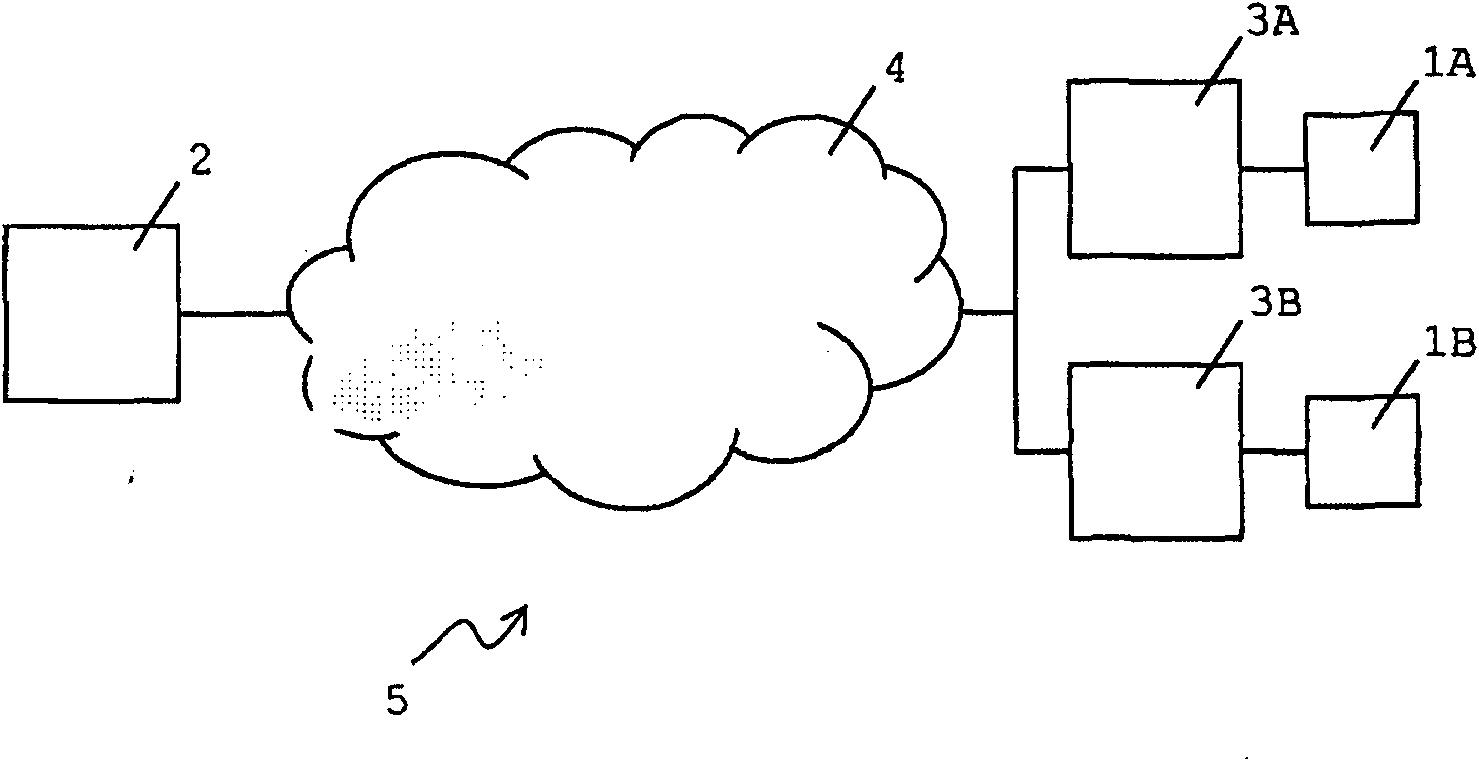
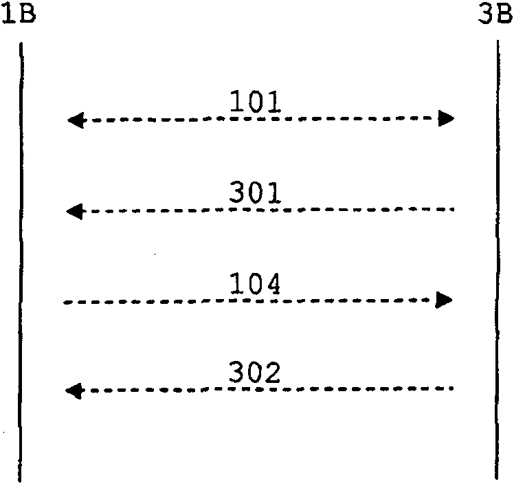
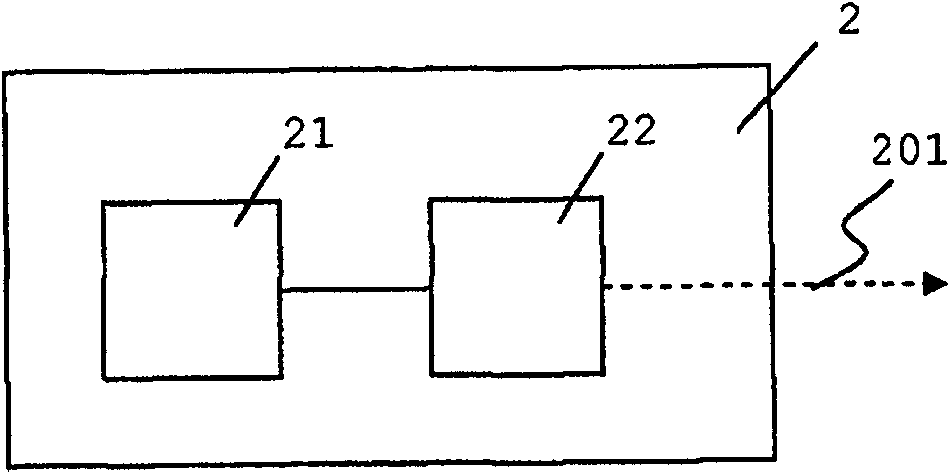
[0029] exist figure 1 A simplified schematic diagram of the architecture of the conditional access system 5 is shown in . The conditional access system 5 comprises a head-end system 2, a receiver 3A, 3B, a smart card 1A, 1B for the receiver 3A, 3B and a system for transmitting data from the head-end system 2 to the receiver 3A, 3B and the smart card 1A, 1B. Signal broadcast network4. Typically, a conditional access network includes many receivers and smart cards eg on the order of hundreds or thousands or even more. The head-end system 2 broadcasts encrypted television programs or other encrypted services to receivers 3A, 3B. In order to enable decryption of encrypted television programs in the receivers 3A, 3B, the head-end system 2 also broadcasts EMMs and / or ECMs, which are received in the receivers 3A, 3B and forwarded to the smart card 1A , 1B for processing. The head-end system 2 communicates with the smart cards 1A, 1B using vendor-specific technology (usually propr...


PUM


Abstract

The invention provides a smartcard, a head-end system and a conditional access system enabling incompatible receivers to be used in a vendor specific conditional access system. Hereto the smartcard stores an operation mode identifier, which is read upon insertion of the smartcard into the receiver and activation of the smartcard. The operation mode identifier is used to select a protocol for communication with the receiver. If the protocol is incompatible with the receiver, the operation mode identifier is changed and another protocol is selected upon reinsertion of the smartcard in the receiver. The head-end system uses data packet encapsulation to enable the receiver to forward EMMs and ECMs to the smartcard.

Description

technical field [0001] The present invention relates to a smart card for a receiver of a conditional access system, a head-end system for a conditional access system and a conditional access system. More specifically, the present invention relates to implementing a multi-vendor conditional access system. Background technique [0002] Conditional access systems are well known and widely used in conjunction with currently available pay television systems. Currently, such systems are based on the transmission of services encrypted with control words (also called service encryption keys) received by subscribers with a set-top box (also called receiver) and a smart card for each subscription package. Typically, these services are sent in broadcast streams by head-end systems. Implementations are known in which the set-top box functionality is integrated in devices such as televisions, personal video recorders, mobile phones, smartphones or computer appliances. A smart card is ...

Claims


Application Information

Patent Timeline
Patent Type & Authority Applications(China)
IPC IPC(8): H04N21/4623H04N21/418H04N5/00H04N7/16
CPCH04N21/4623H04N21/43607H04N21/26606H04N7/163H04N21/4367H04N21/4181
Inventor A·J·P·M·范德温
Owner IRDETO ACCESS
Why Eureka
Eureka Blog
Learn More