Linear guide rail copying device for lathing and milling crossbeam and manufacturing method thereof

A technology of linear guide rail and profiling device, which is applied in the direction of manufacturing tools, milling machine equipment, milling machine equipment details, etc., can solve the problems of unable to compensate the gravity deformation of the beam, increase the external dimension and gravity, and poor practicability, so as to reduce the difficulty of processing and manufacture The effect of reducing costs, shortening the manufacturing cycle, and improving work accuracy

Inactive Publication Date: 2011-09-07
SHENYANG MASCH TOOL CO LTD
View PDF3 Cites 2 Cited by
  • Summary
  • Abstract
  • Description
  • Claims
  • Application Information

AI Technical Summary

Problems solved by technology

The first type adopts a rigid structure with enlarged cross-beam section. Although the rigidity of the cross-beam section is increased, the external dimension and gravity of the cross-beam are also increased. Therefore, this type of structure is more suitable for machine tools with a fixed cross-beam, but for the vertical movement of the cross-beam. The machine tool is not applicable; the second type adopts the unloading beam structure, by using the unloading beam, the deformation of the main rail of the beam caused by the gravity of the skateboard kit can be offset, but the gravity deformation of the beam itself cannot be compensated, so on the one hand, it is necessary to increase the unloading The structure of the beam, on the other hand, still needs to increase the rigidity of the cross-section of the beam appropriately; the third type adopts the anti-gravity deformation structure of the sliding guide rail beam, that is, before processing the main rail surface of the beam, the finite element analysis is carried out through the analysis software, and according to the analyzed According to the d...

Method used


Image

  • Linear guide rail copying device for lathing and milling crossbeam and manufacturing method thereof
  • Linear guide rail copying device for lathing and milling crossbeam and manufacturing method thereof
  • Linear guide rail copying device for lathing and milling crossbeam and manufacturing method thereof

Examples


Embodiment Construction

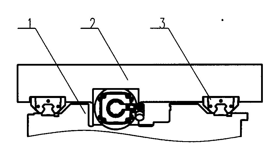
[0016] The turning and milling beam linear guide rail profiling device mainly includes the beam main body 1, the skateboard kit 2 and the linear rolling guide rail 3, see figure 1 . The gravity sagging phenomenon caused by the self-weight of the beam and the gravity of the skateboard kit on the guide rail of the beam is counteracted by profiling the guide rail surface of the main body 1 of the beam.

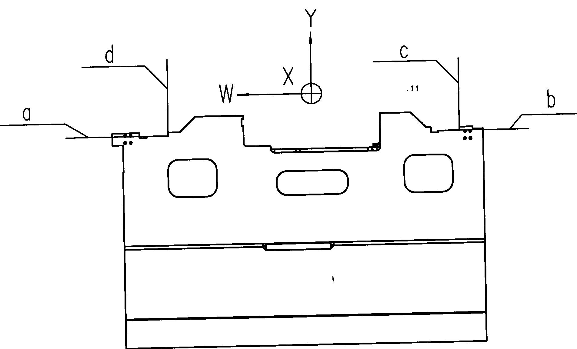
[0017] For profiling of beam body 1 castings, see figure 2 Among them, the four surfaces a, b, c, and d are the positioning surface and the joint surface of the linear guide rail. These four surfaces need to be profiling processed, and they are also called processing surfaces during processing.

[0018] The specific implementation process is as follows:

[0019] 1. Establishment of beam profiling curve

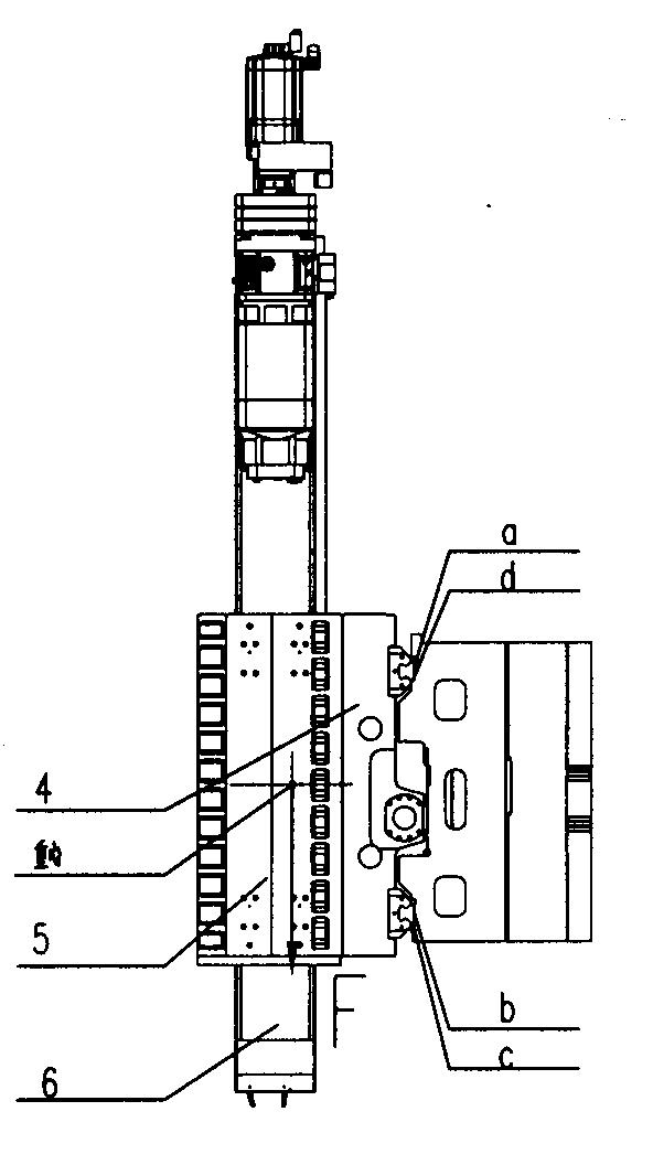
[0020] First, carry out the force analysis on the beam, such as image 3 As shown, the ram kit is composed of a slide plate 4, a ram shell 5, and a ram 6, and the deformatio...


PUM


Abstract

The invention relates to a linear guide rail copying device for lathing and milling a crossbeam and a manufacturing method thereof, wherein the linear guide rail copying device for lathing and milling a crossbeam comprises a crossbeam main body, a linear rolling guide rail and a sliding plate kit, and the maximum speed of the X-axis of a machine tool crossbeam is 16000 mm/min. The linear guide rail copying device for lathing and milling a crossbeam is characterized in that a copying curved surface is manufactured by processing the screwing surfaces and the locating surfaces of two parallel guide rails of the crossbeam main body; the curve of the curved surface is the same as that of the vertical plane of the linear rolling guide rail after the crossbeam is loaded, stressed and deformed, but is in an opposite direction; the linear rolling guide rail and the guide rail surface of the crossbeam main body are fastened into a whole by set screws and impacting blocks on the guide rail surface of the crossbeam main body, and the tight attachment of the linear rolling guide rail and the copying curved surface of the crossbeam guide rails is ensured by increasing the numbers of the screws and the impacting blocks; and the sliding plate kit is screwed on the sliding block of the linear rolling guide rail by screws, and a damping block is arranged between the linear rolling guide rail and the sliding block. The invention has the advantages of increasing the working accuracy of a machine tool, simplifying the design structure of the machine tool, reducing the processing hardness of the machine tool crossbeam and shortening the manufacturing cycle of the machine tool.

Description

technical field [0001] The invention relates to mechanical equipment manufacturing, a beam linear guide rail profiling device and a manufacturing method of a large vertical turning and milling center. Background technique [0002] There are three main structures for beam deformation compensation of vertical turning and milling centers at this stage. The first is to increase the cross-section rigidity of the beam to reduce the deformation of the beam guide rail; the second is to use an unloading beam structure to offset the deformation of the main rail of the beam; the third is to use a beam anti-gravity deformation structure to offset the deformation caused by gravity. Deformation of the beam guide. [0003] There are pros and cons to each of the three structures today. The first type adopts a rigid structure with enlarged cross-beam section. Although the rigidity of the cross-beam section is increased, the external dimension and gravity of the cross-beam are also increase...

Claims


Application Information

Patent Timeline
IPC IPC(8): B23C3/00B23Q35/04
Inventor 刘兴卓崔佩强吴俊勇轩广进张春艳喻鹏代丽芬张秀印王晶赵东海常宏苗青邵茂利刘丽芳
Owner SHENYANG MASCH TOOL CO LTD
Why Eureka
Try Eureka