Diversion method for composite vacuum perfusion molding process

A composite material and vacuum infusion technology, applied in the field of composite material molding technology, can solve the problems of loss of liquid resin, long molding time, low production efficiency, etc., and achieve the effects of improving compression resistance, shortening molding time, and improving production efficiency

Active Publication Date: 2011-09-07
LUOYANG SUNRUI WIND TURBINE BLADE
View PDF3 Cites 5 Cited by
  • Summary
  • Abstract
  • Description
  • Claims
  • Application Information

AI Technical Summary

Problems solved by technology

[0007] 2. The speed of liquid resin on the surface of the laminate structure is almost completely lost, resulting in extremely slow dispersion speed on the surface, and the flow speed of liquid resin is greatly reduced
The impact: longer molding times, lower productivity, and increased risk of the liquid resin not fully saturating the dry layup during infusion
[0008] 3. The gas remaining in the liquid resin and the dry layup structure cannot be removed through the diversion medium. At the same time, the downwardly penetrating liquid resin and the gas in the bottom layup structure float to the upper layer of the layup, so that all these gases are collected in the diversion medium The upper layer of the laminate in the partition area reduces the tensile, bending, shearing and compression resistance of the product, reduces the mechanical properties of the product and affects the service life, chemical corrosion resistance and weather resistance of the product
[0009] Therefore, it is necessary to design the isolation area of ​​the diversion medium in the vacuum infusion molding process, but at the same time it will bring more negative problems

Method used


Image

  • Diversion method for composite vacuum perfusion molding process
  • Diversion method for composite vacuum perfusion molding process
  • Diversion method for composite vacuum perfusion molding process

Examples


Embodiment 1

[0020] An application example of vacuum infusion molding of large composite wind turbine blades with a length of 50 m and a width of 5 m.

[0021] The 50m wind power blade is divided into upper and lower shells, which are formed by vacuum infusion during molding. After curing, the upper and lower shells are bonded together with adhesive. The layering method of the upper and lower shells is exactly the same as the layering structure, and any of them can be called a half shell.

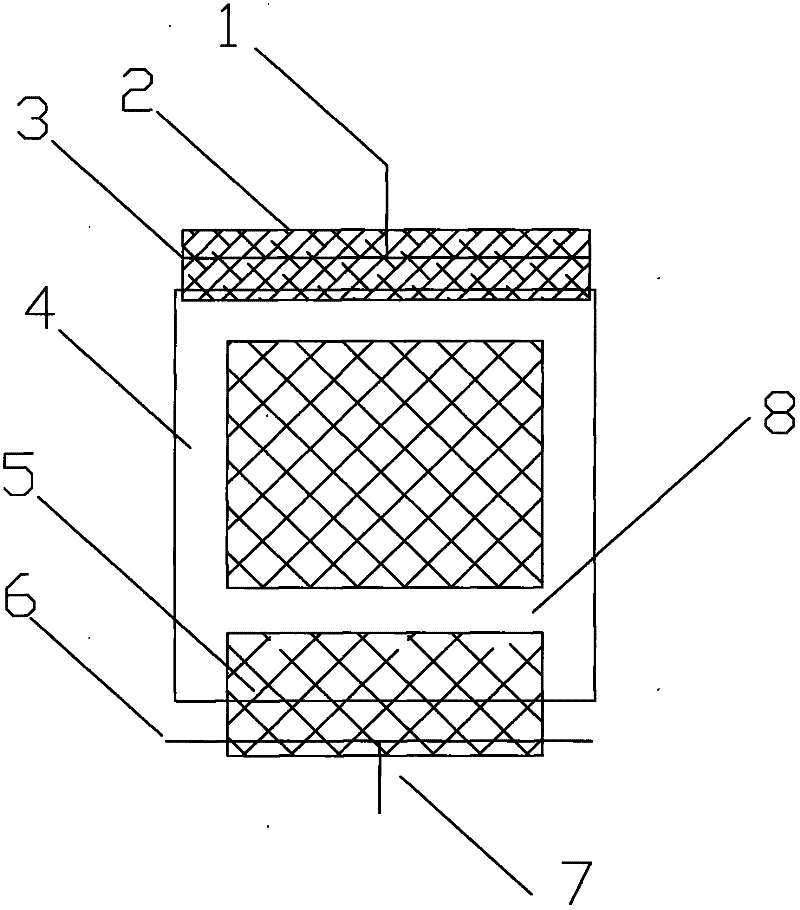
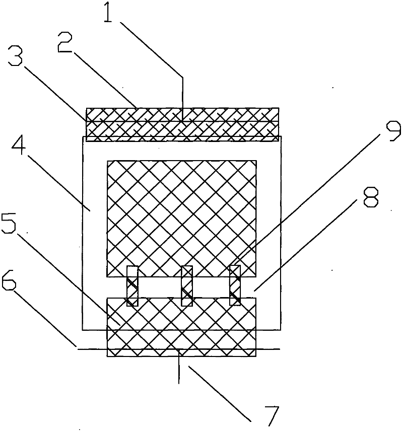
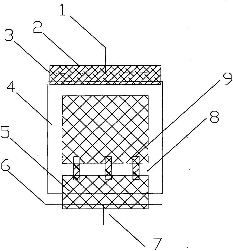
[0022] When the half-shell is being formed, 3 layers of dry fiber layers are laid on the entire surface of the half-shell forming mold along the length direction from 10m to 50m, and the main composite material prefabricated by unidirectional glass fiber is laid along the length direction from 10m to 50m. Beam, the main beam is located in the center of the width direction of the forming mold, the honeycomb sandwich material with the same height as the main beam is laid on both sides of the main beam, an...

Embodiment 2

[0025] An application example of vacuum infusion molding of large composite wind turbine blades with a length of 50m and a width of 5m.

[0026] The 50m wind power blade is divided into upper and lower shells, which are formed by vacuum infusion during molding. After curing, the upper and lower shells are bonded together with adhesive. The layering method of the upper and lower shells is exactly the same as the layering structure, and any of them can be called a half shell.

[0027] When the half-shell is being formed, 100 layers of dry fiber layers are laid on the entire surface of the molding die of the lower shell along the length direction from 0m to 10m.

[0028] Then lay two diversion media along the width direction on the upper surface of the above-mentioned dry laying layer. The diversion medium is composed of a space mesh fabric with a certain thickness. Its function is that during vacuum infusion molding, the liquid resin can quickly disperse into these space mesh s...


PUM


Abstract

The invention belongs to the field of composite molding processes and mainly provides a diversion method for a composite vacuum perfusion molding process. The diversion method comprises the steps of paving diversion mediums (5) on the upper surface of a dry fiber paving layer, wherein the intervals among the diversion mediums located on the upper surface of the dry fiber paving layer form a diversion medium partition area (8); overlapping a diversion bridge (9) between the adjacent diversion mediums (5) with the intervals, wherein the adjacent diversion mediums (5) with the intervals are communicated by the diversion bridge; and cooperating the diversion bridge (9) overlapped between the adjacent diversion mediums (5) with the intervals with the diversion medium partition area (8) formed by the intervals among the diversion mediums so as to control the dispersion speed of liquid resin on the upper layer of the paving layer and guarantee the permeation and dispersion speed of the liquid resin in a direction perpendicular to the paving layer which is the bottom layer, wherein the diversion bridge overlapped between the adjacent diversion mediums with the intervals is composed of the material which is same with the diversion mediums (5).

Description

technical field [0001] The invention belongs to the technical field of composite material molding technology, and mainly proposes a diversion method for composite material vacuum infusion molding technology. Background technique [0002] The principle of the vacuum infusion molding process is: dry fiber layup in the composite material mold, lay diversion medium on the upper surface of the dry fiber layup, and then establish a vacuum sealing system together with the dry layup and diversion medium together with the mold, and finally in Dispersion of the liquid resin through the diversion medium under vacuum pressure allows the layup to be completely wetted. [0003] The diversion medium is a space mesh fabric with a certain thickness, and the liquid resin is quickly dispersed into these space mesh structures under vacuum pressure to realize the penetration of the surface and bottom layer of the dry fiber layer, and at the same time pass through the space of the diversion mediu...

Claims


Application Information

Patent Timeline
Patent Type & Authority Applications(China)
IPC IPC(8): B29C70/34
Inventor 林明黎华史俊虎
Owner LUOYANG SUNRUI WIND TURBINE BLADE
Why Eureka
Try Eureka