Laser thickness gauge

A thickness gauge and laser technology, which is applied in the field of laser thickness gauges, can solve the problems of low measurement accuracy of laser thickness gauges, and achieve the effect of high-precision measurement stability

Active Publication Date: 2011-09-07
DONGGUAN AMPEREX TECH +1
View PDF10 Cites 23 Cited by
  • Summary
  • Abstract
  • Description
  • Claims
  • Application Information

AI Technical Summary

Problems solved by technology

[0008] The purpose of the present invention is to provide a laser thickness gauge with high measurement accuracy for the technical problem of low measurement accuracy of the prior art laser thickness gauge

Method used


Image

  • Laser thickness gauge
  • Laser thickness gauge
  • Laser thickness gauge

Examples


Embodiment Construction

[0029] In order to make the object, technical solution and technical effect of the present invention clearer, the present invention will be further described in detail below in conjunction with the accompanying drawings and specific embodiments. It should be understood that the specific implementations described in this specification are only for explaining the present invention, not for limiting the present invention.

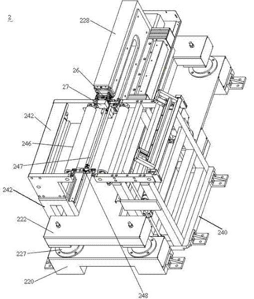
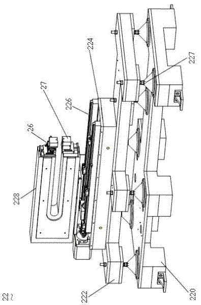
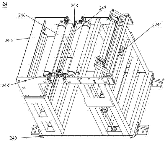
[0030] see figure 1 Shown is a schematic structural view of a specific embodiment of the laser thickness gauge 2 of the present invention. The laser thickness gauge 2 includes a measuring component 22 and a belt threading component 24 .

[0031] The measurement assembly 22 includes a base 220 , a first bracket 222 , a support base 224 , a guide rail 226 , a second bracket 228 and a position adjuster 26 . Several rubber pads 227 are disposed between the base 220 and the first bracket 222 .

[0032] The base 220 adopts an I-shaped design and a heavy weight de...


PUM


Abstract

The invention discloses a laser thickness gauge for measuring the thickness of a battery pole piece. The laser thickness gauge comprises a measurement assembly and a wearing assembly. The measurement assembly comprises a position adjustor and a sensor arranged on the position adjustor, the battery pole piece is arranged on the wearing assembly, the sensor measures the thickness of the battery pole piece, and the measurement assembly spans the wearing assembly. Compared with the prior art, the laser thickness gauge has the advantages of high measurement precision and good stability.

Description

technical field [0001] The invention relates to a thickness measuring instrument, more specifically, the invention relates to a laser thickness measuring instrument for measuring the thickness of battery pole pieces. Background technique [0002] As we all know, with the increasing demand for batteries in people's daily life, the detection of battery quality will inevitably become a matter of great concern to battery manufacturers. [0003] Among the various indicators of battery quality inspection, the inspection of the thickness of the battery pole piece after the battery is cold-pressed is very important, which will directly affect the subsequent processes. How to measure the thickness of battery pole pieces with high precision is an urgent problem for battery manufacturers. [0004] So far, some battery manufacturers have used the static contact thickness measurement method to measure the thickness of the battery pole piece (screw micrometer measurement). This measureme...

Claims


Application Information

Patent Timeline
IPC IPC(8): G01B11/06
Inventor 贾宝安罗志高
Owner DONGGUAN AMPEREX TECH
Why Eureka
Try Eureka