Supercharge Your Innovation With Domain-Expert AI Agents!

High Density Backplane Connectors

A technology of electrical connectors and sub-boards, which is applied in the direction of connection, fixed connection, and two-component connection devices, and can solve the problem of increasing signal contacts or signal contact intervals, reducing the overall density of electrical connectors, and increasing the occupation of grounding contacts Space and other issues

Inactive Publication Date: 2015-11-25
TE CONNECTIVITY CORP
View PDF3 Cites 0 Cited by
  • Summary
  • Abstract
  • Description
  • Claims
  • Application Information

AI Technical Summary

Problems solved by technology

However, increasing the ground contact footprint reduces the overall density of the electrical connector and therefore increases the spacing between signal contacts or pairs of signal contacts
[0005] Therefore, it remains a challenge to provide high-density electrical connectors with minimal signal loss

Method used


Image

  • High Density Backplane Connectors
  • High Density Backplane Connectors
  • High Density Backplane Connectors

Examples


Embodiment Construction

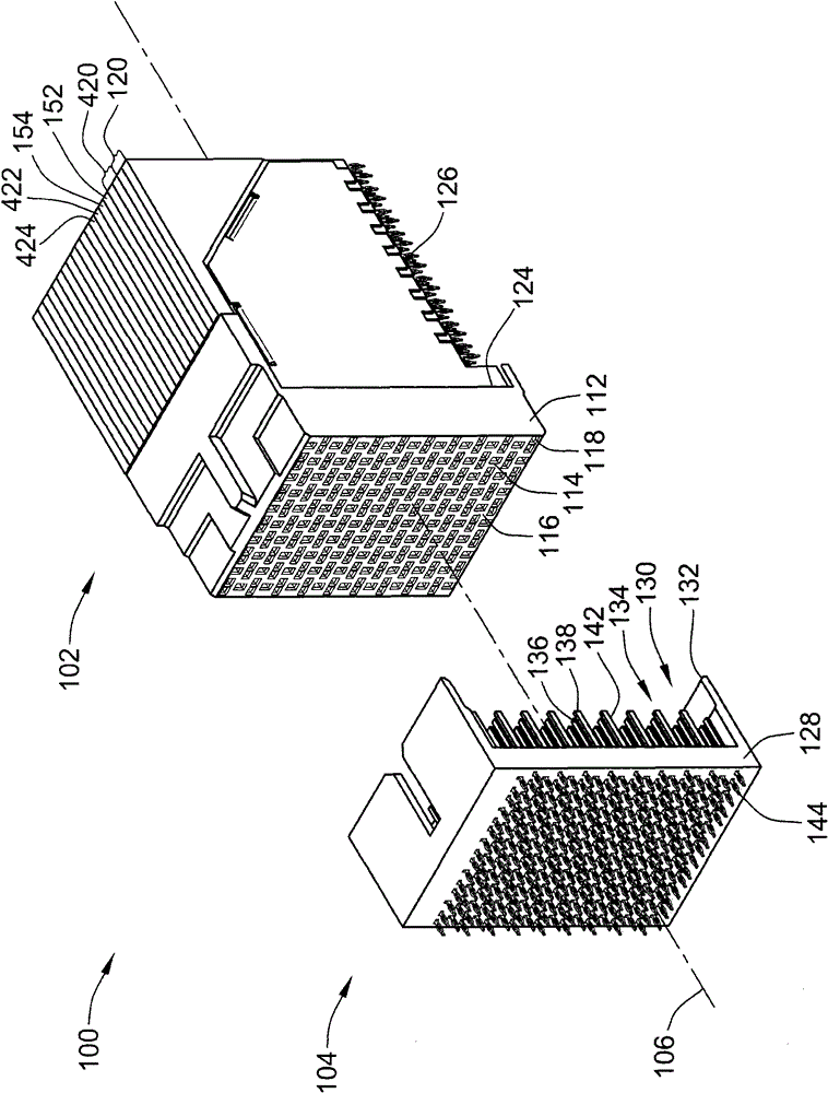
[0017] figure 1 Is a perspective view of the connector system 100 showing the two electrical connectors 102, 104 in an unmated position prior to mating with each other, in accordance with an embodiment of the present invention. The electrical connectors 102, 104 are each configured to be board-mountable on a circuit board, such as a backplane, daughter card, midplane, or other circuit board configured to be coupled together. The electrical connectors 102, 104 are used to electrically connect the circuit boards to each other. In an alternative embodiment, the electrical connectors 102, 104 may be cable mounted rather than board mounted.

[0018] In the illustrated embodiment, the first electrical connector 102 constitutes a receptacle connector and may be referred to as receptacle connector 102 hereinafter. The second electrical connector 104 constitutes a header connector, and may be referred to as header connector 104 hereinafter. The receptacle connector 102 is configured...


PUM


Abstract

An electrical connector includes a housing and contact modules held in the housing. Each of the contact modules has a first chicklet and a second chicklet coupled together to form a corresponding one of the contact modules. Contacts are held in the contact modules and arranged in differential pairs. A first contact in each of the differential pairs is held by the first chicklet and a second contact in each of the differential pairs is held by the second chicklet.

Description

technical field [0001] The present invention relates to electrical connectors having a high density of signal contacts. Background technique [0002] Some electrical systems, such as network switches or computer servers with switching functions, include a large backplane with several daughter cards, such as switch cards or line cards, plugged into the backplane. The electrical system interconnects the circuit boards defining the cards to the circuit boards defining the backplane using electrical connectors. Typically, the electrical connector is a right-angle connector mounted on the edge of the chassis or on one of the cards. An electrical connector mates with a header connector mounted on the midplane. [0003] Known electrical systems utilizing right-angle connectors and header connectors mounted on a midplane are not without drawbacks. For example, a large number of switch cards and line cards are often connected to the backplane, which increases the overall size of t...

Claims


Application Information

Patent Timeline
Patent Type & Authority Patents(China)
IPC IPC(8): H01R13/02H01R13/40H01R13/514H01R13/648H01R12/55
CPCH01R13/6587H01R13/514H01R23/688H01R23/7073H01R2107/00H01R12/724
Inventor 韦恩·S·戴维斯
Owner TE CONNECTIVITY CORP
Features
  • R&D
  • Intellectual Property
  • Life Sciences
  • Materials
  • Tech Scout
  • Unparalleled Data Quality
  • Higher Quality Content
  • 60% Fewer Hallucinations
Learn More