Double-sealing structure of radio frequency coaxial connector and related radio frequency coaxial connector

A radio frequency coaxial and connector technology, which is applied to the parts of the connecting device, the device that relieves the stress of the wire connection, the connection and other directions, can solve the problems of easy loss of parts, high production cost, high use cost, and achieves ingenious and unique design , The effect of low production cost and low use cost

Inactive Publication Date: 2011-09-07
ANDREW CORP
View PDF4 Cites 11 Cited by
  • Summary
  • Abstract
  • Description
  • Claims
  • Application Information

AI Technical Summary

Problems solved by technology

[0005] 1. The above-mentioned connector structure is a multi-part structure, the processing is complicated, the production cost is high, and the price is high;
[0006] 2. Since the above-mentioned connector structure is a multi-part structure, parts are easy to be lost, and missing parts are prone to occur during field installation, especially the V-shaped sealing ring 3 and flat gasket 4, and the installation time is long at the same time;
[0007] 3. Since the above-mentioned connector structure adopts a V-shaped sealing ring 3, and the V-shaped sealing ring 3 is destroyed after being compressed (divided into two sections), it cannot be installed multiple times, and the use cost is high;
[0008] 4. Since the outer side of the V-shaped sealing ring 3 abuts against the inner wall of the connector body 1 to achieve sealing with the inner wall, the sealing effect is not very good due to insufficient abutting force

Method used


Image

  • Double-sealing structure of radio frequency coaxial connector and related radio frequency coaxial connector
  • Double-sealing structure of radio frequency coaxial connector and related radio frequency coaxial connector
  • Double-sealing structure of radio frequency coaxial connector and related radio frequency coaxial connector

Examples


Embodiment Construction

[0061] In order to understand the technical content of the present invention more clearly, the following examples are given in detail.

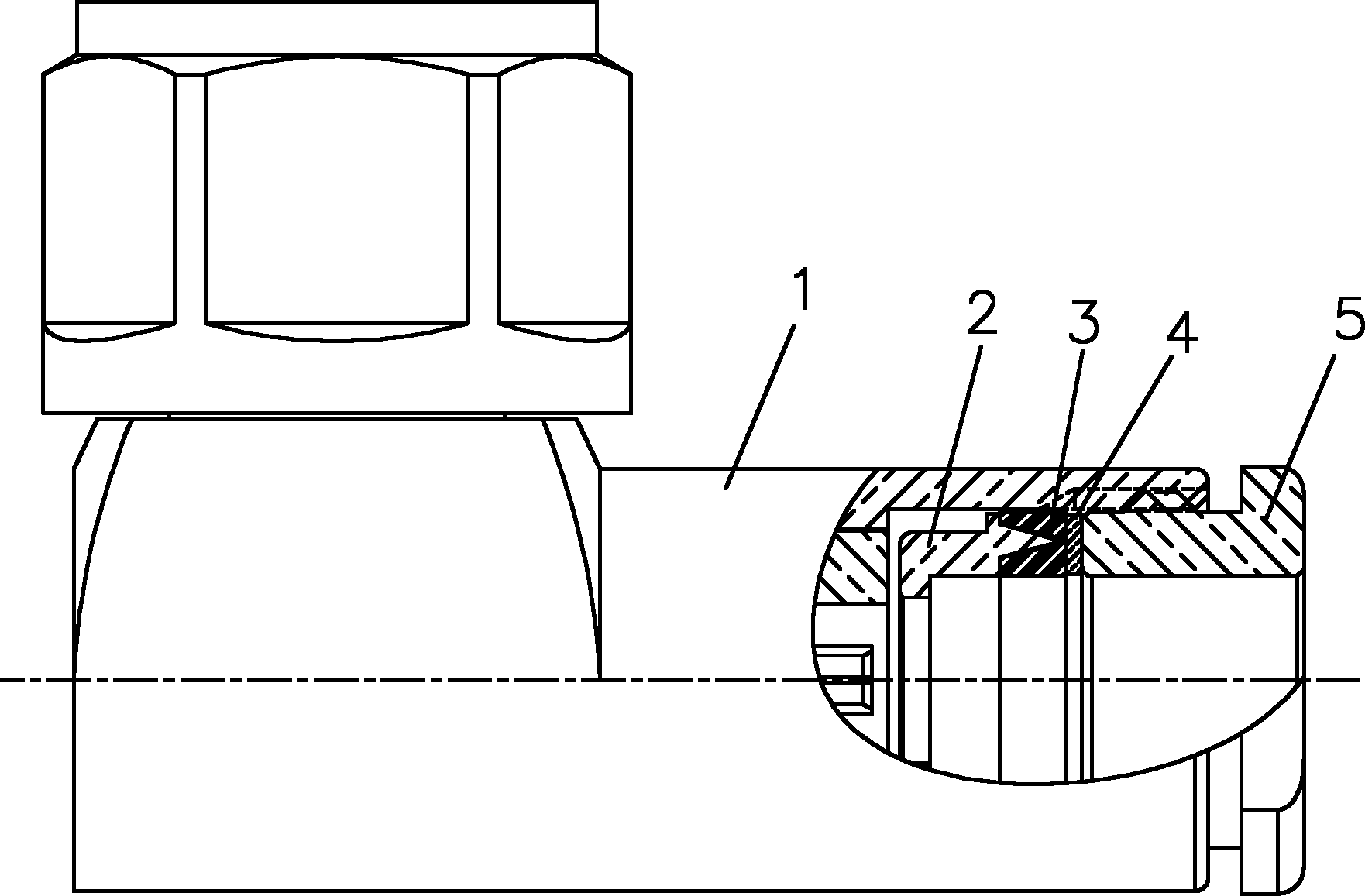
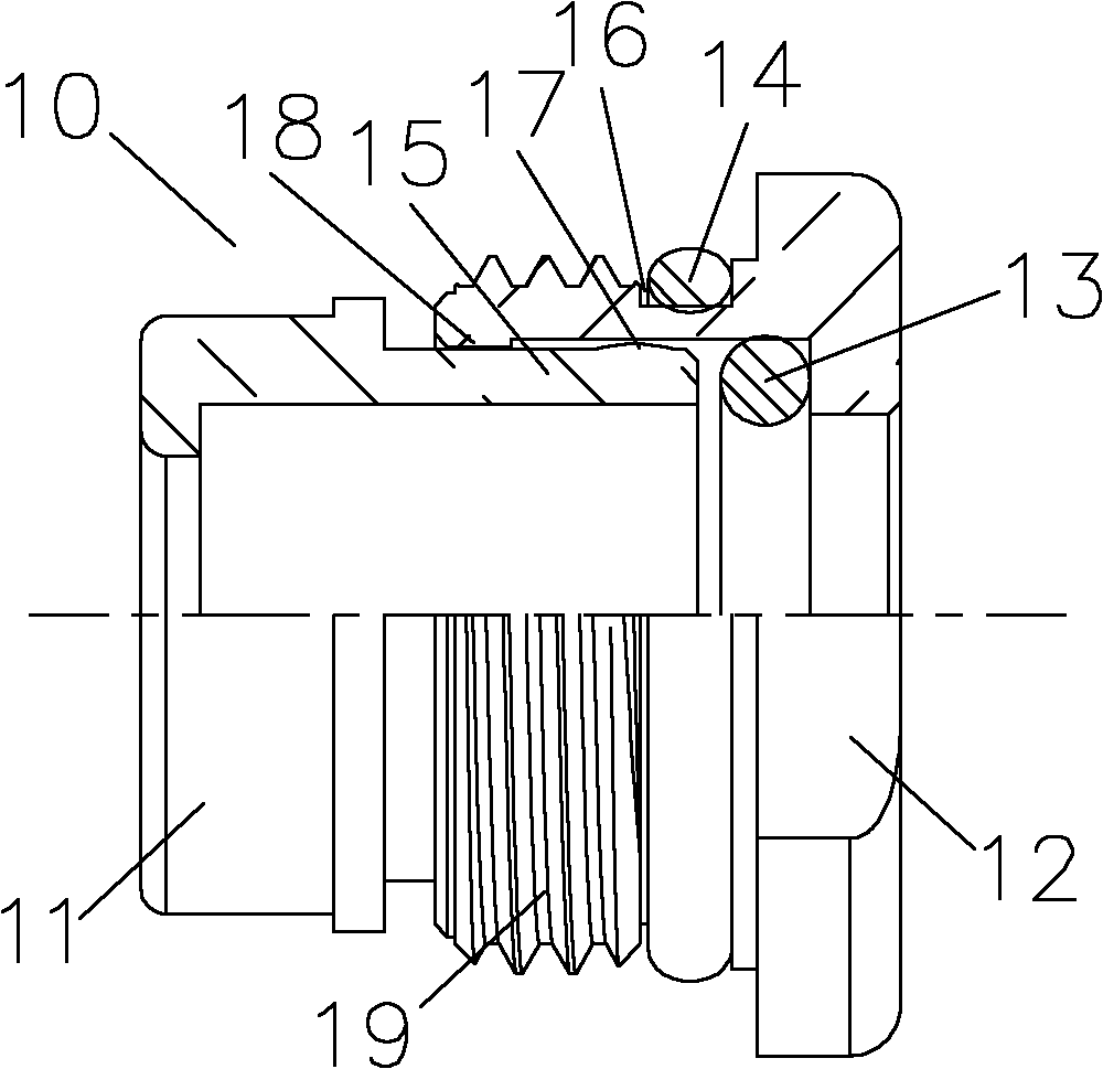
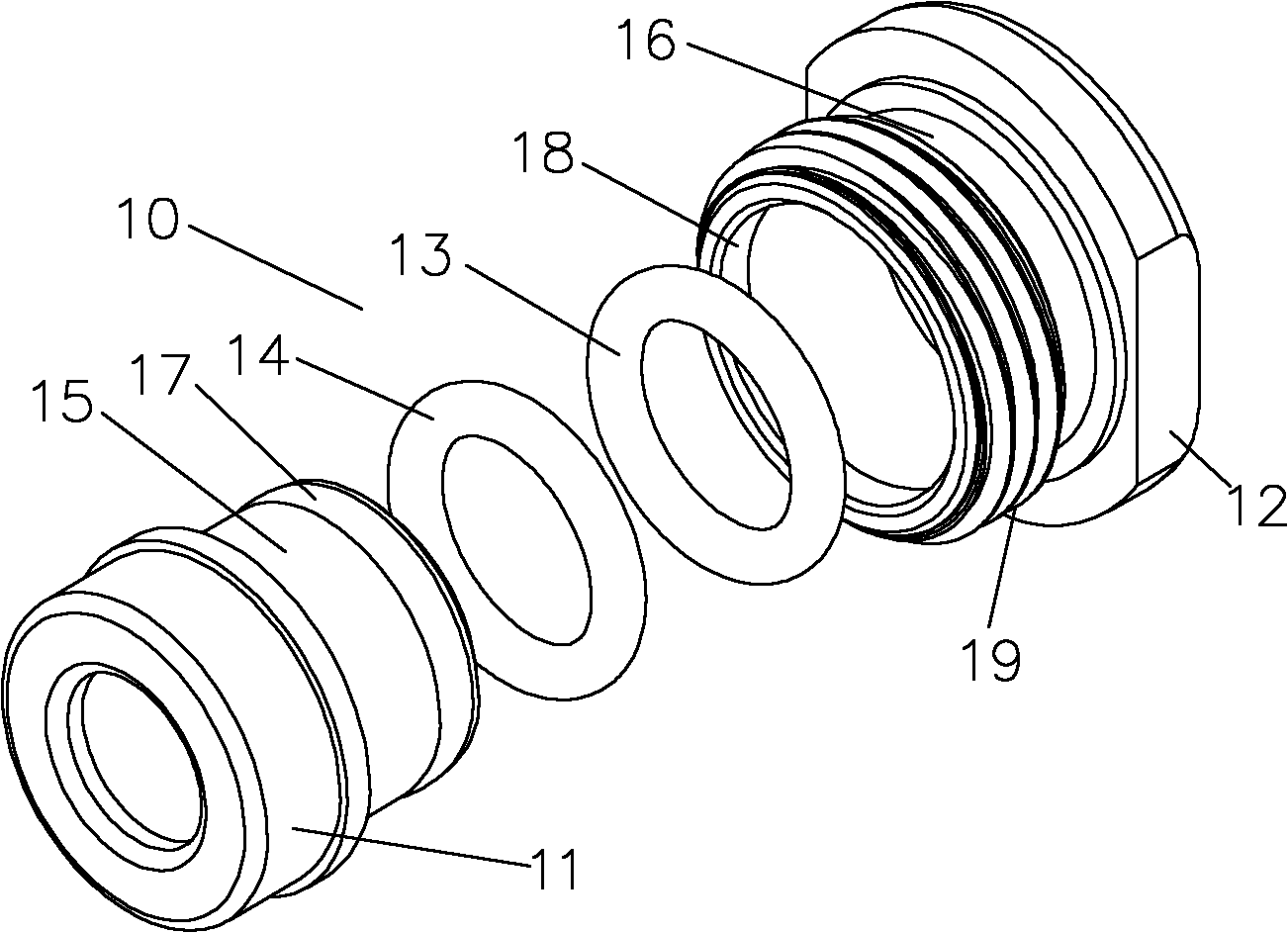
[0062] See Figure 2-4 As shown, the double sealing structure 10 of the radio frequency coaxial connector of the present invention includes a cable clamping part 11, a lock nut 12 for connecting the connector body 20 of the radio frequency coaxial connector, a first sealing ring 13 and The second sealing ring 14, the cable clamping part 11 includes a first end 15, the first end 15 is movably arranged in the lock nut 12, the first sealing ring 13 is located in the lock Inside the inside surface of the lock nut 12 and between the end face of the first end 15 and the inner wall of the lock nut 12, the second sealing ring 14 is arranged on the outside surface of the lock nut 12 for In order to seal with the connector body 20.

[0063] Preferably, it can be as Figure 2-5B As shown, a groove 16 is provided on the outer surface of the locking nu...


PUM


Abstract

The invention relates to a double-sealing structure of a radio frequency coaxial connector. The double-sealing structure comprises a cable clamping part, a locking nut for connecting a connector body of the radio frequency coaxial connector, a first sealing ring and a second sealing ring, wherein the cable clamping part comprises a first end part, and can be movably arranged in the locking nut; the first sealing ring is positioned in the inner surface of the locking nut and between the end face of the first end part and the inner wall of the locking nut; the second sealing ring is arranged on the outer surface of the locking nut, and is used for realizing sealing with the connector body; the first end part is limited by the locking nut in a direction away from the locking nut, and can be in press fit connection or threaded connection with the locking nut; and the first and second sealing rings may be O-shaped, rectangular or square. The invention also relates to the related radio frequency coaxial connector. The double-sealing structure is ingeniously and uniquely designed, good in sealing effect, smaller in part number, simply manufactured, low in production cost and using cost, short in mounting time, repetitively mountable and suitable for large-scale popularization and application, and the parts of the double-sealing structure are difficult to lose.

Description

technical field [0001] The invention relates to the technical field of radio frequency coaxial connectors, in particular to the technical field of sealing structures of radio frequency coaxial connectors, in particular to a double sealing structure of radio frequency coaxial connectors and related radio frequency coaxial connectors. Background technique [0002] A radio frequency coaxial connector (also known as an RF connector) is a component that connects a radio frequency coaxial cable to equipment or different types of cables, and acts as a component that electrically connects or separates transmission lines. It belongs to the mechatronics product. Simply put, it mainly acts as a bridge. [0003] See figure 1 as shown, figure 1 Shown is a commonly used radio frequency coaxial connector, including connector body 1, cable clamping part 2, V-shaped sealing ring 3, flat gasket 4, and lock nut 5, when using, remove the radio frequency The outer shielding layer at the end ...

Claims


Application Information

Patent Timeline
Patent Type & Authority Applications(China)
IPC IPC(8): H01R13/52H01R13/59H01R24/40
CPCH01R24/40H01R13/5205H01R13/5202
Inventor 黄木兰张玉俊郑继恩安红娟
Owner ANDREW CORP
Why Eureka
Try Eureka