Water-purifying cartridge and water purifier

A filter cartridge and water purification technology, which is used in water/sewage treatment, adsorption water/sewage treatment, water/sludge/sewage treatment, etc., and can solve the problems of complicated setting of multiple water control valves.

Inactive Publication Date: 2012-10-10
PANASONIC CORP
View PDF1 Cites 0 Cited by
  • Summary
  • Abstract
  • Description
  • Claims
  • Application Information

AI Technical Summary

Problems solved by technology

Therefore, there is a problem that the setting work of adjusting a plurality of water flow control valves is complicated.

Method used


Image

  • Water-purifying cartridge and water purifier
  • Water-purifying cartridge and water purifier
  • Water-purifying cartridge and water purifier

Examples


Embodiment 1

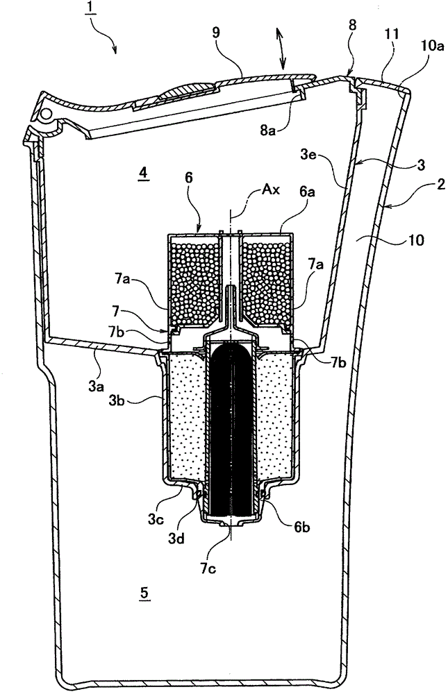
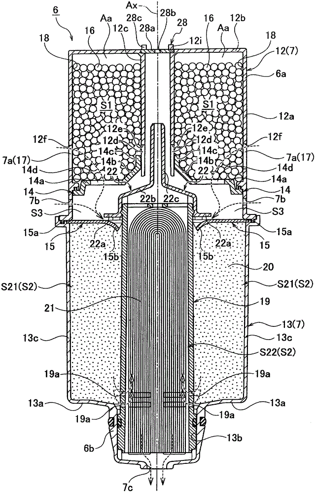
[0030] Figure 1 ~ Figure 3 Example 1 of the present invention is shown.

[0031] First, refer to figure 1 The schematic structure of the water purifier 1 which concerns on Example 1 is demonstrated. This water purifier 1 is comprised as a pot type water purifier. A bottomed cylindrical partition body 3 is accommodated in a bottomed cylindrical pot case 2 . The inside of the pot case 2 is partitioned by a partition wall 3 into a raw water chamber 4 forming approximately half of the upper side and a purified water chamber 5 forming approximately half of the lower side.

[0032] A cylindrical recess 3 b recessed downward is formed on the bottom wall 3 a of the partition body 3 . The cylindrical water purification cartridge 6 is inserted into the recessed part 3b from above, and is fitted and fixed to the back side. The opening 3d is formed in the inner wall 3c of the recessed part 3b.

[0033] The upper part 6a of the water purification cartridge 6 is exposed in the raw wa...

Embodiment 2

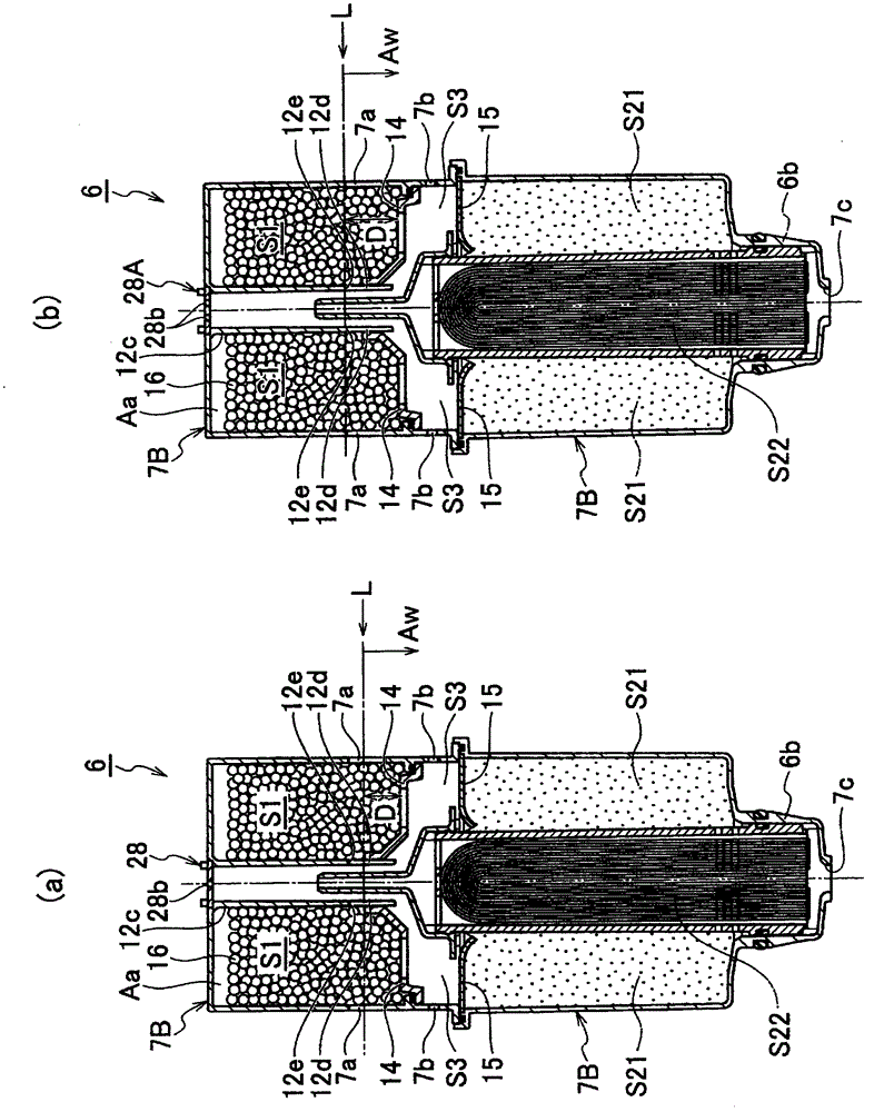
[0068] Figure 4 as well as Figure 5 Example 2 of the present invention is shown.

[0069] In Example 2, instead of the covers 28 and 28A, the cover 28B as the submerged height setting mechanism is attached to the water purification cartridge 6 according to the above-mentioned Example 1. The cover 28B is installed Figure 5 Shown water purification cartridge 6 also can be installed in figure 1 Shown water purifier 1 is used.

[0070] The cover body 28B is configured as a valve (one-way valve, check valve) that allows air to flow upward from the bottom and restricts air or water flow from the top to the bottom. The cover body 28B has a through hole 28 b and a valve body 29 . The spool 29 is configured to openably and closably close the through-hole 28B. The spool 29 has: a rod-shaped portion 29a fitted and fixed to a through hole 28d formed in the center of the plate portion 28a; The lower portion expands into an umbrella shape and is roughly circular when viewed from a...

Embodiment 3

[0074] Figure 6 It is a cross-sectional view of the water purifier according to Example 3 of the present invention.

[0075] In Example 3, the water purifier 1C is provided with a pump unit 30 including an air pump 30p as a submerged height setting mechanism, and the pump unit 30 passes through the piping 30a to the air accumulation area Aa of the water purification cartridge 6C. Supply air inside.

[0076] Specifically, on the side wall 3e of the partition body 3 forming a part of the main body of 1C of water purifiers, 3 f of board parts protruding inward and having a D-shape in planar view are formed. The pump unit 30 is placed and fixed on the board portion 3f. The lower end portion of the pipe 30a is inserted into the cylindrical portion 12j protruding downward from the top wall 12b of the upper case 12C of the water purification cartridge 6 in a sealed state.

[0077] In the pump unit 30, in addition to the air pump 30p configured as a relatively small positive displ...


PUM


Abstract

A water-purifying cartridge (6) is provided with a case (7) inside which a purifying chamber (S2) for purifying water introduced therein and an additive-containing chamber (S1) for containing an additive (16) to be added to the introduced water are formed and which is provided with a first water-introducing opening (7a) for introducing the water into the additive-containing chamber (S1). The additive-containing chamber (S1) has formed therein an air-retaining region (Aa) and a water-submerged region (Aw). The air-retaining region (Aa) is located in the upper part of the additive-containing chamber and retains air, and the water-submerged region (Aw) is located below the air-retaining region and retains the introduced water. The additive (16) is submerged in the introduced water in the water-submerged region (Aw). The additive (16) is contained in the additive-containing chamber (S1) in the region thereof extending from a portion which becomes the water-submerged region (Aw) up to a portion which becomes the air-retaining region (Aa). A submerged-height-setting mechanism sets the submerged height of the water-submerged region (Aw) by setting the pressure of air retained in the air-retaining region (Aa). A cap (28) having formed therein a through-hole (28b) functioning as a fluid restriction for an air vent path is used as the submerged-height-setting mechanism.

Description

technical field [0001] The invention relates to a water purification filter cartridge and a water purifier using the water purification filter cartridge. Background technique [0002] As a conventional water purifier, there is known a water purifier as follows: it is provided with a plurality of water channels for accommodating water-activating agents with different mineral contents, and a water control valve is respectively provided in the above-mentioned water channels, The mineral concentration of water is variably set by controlling the opening and closing of each water flow control valve (Patent Document 1). [0003] [Patent Document 1] Japanese Patent Application Laid-Open No. 10-15564 [0004] However, in the conventional water purifier described in Patent Document 1, it is necessary to set the mineral concentration of water by adjusting a plurality of water flow control valves. Therefore, there is a problem that the work of adjusting the settings of the plurality o...

Claims


Application Information

Patent Timeline
Patent Type & Authority Patents(China)
IPC IPC(8): C02F1/28C02F1/44C02F1/68
CPCC02F2209/03C02F1/283C02F1/003C02F2307/04C02F1/444C02F1/28C02F1/44C02F1/68
Inventor 平井利明小玉诚
Owner PANASONIC CORP
Why Eureka
Try Eureka