Improved structure of filter vat

An improved structure and filter barrel technology, applied in the direction of filtration and separation, fixed filter elements, chemical instruments and methods, etc., can solve the problems of easy oil leakage, reduced filtration efficiency, high cost, etc., to achieve easy installation and disassembly, improve drainage The effect of slag efficiency and easy operation

Active Publication Date: 2011-09-14
江苏福斯利特环保科技有限公司
View PDF4 Cites 6 Cited by
  • Summary
  • Abstract
  • Description
  • Claims
  • Application Information

AI Technical Summary

Problems solved by technology

When the filter barrel is maintained, the screw on the barrel cover must be disassembled first, the barrel cover and the flange plate are hoisted in turn with lifting equipment, and then the nuts fixed on the upper end of the filter element are disassembled one by one, so that the filter element can be taken out. , the assembly and disassembly operation of the filter barrel is extremely cumbersome, time-consuming and laborious, and the efficiency is low, and special tools are required, and multi-person cooperation is required; moreover, the filter barrel needs In addition to installing O-shaped sealing ring 6, additional sealing rings must be installed for each filter element, otherwise oil will leak easily and reduce the filtering effect; in addition, the filter element of the filter barrel is designed with paper, and the filter rod is made of steel. The cost is relatively expensive, and the paper will absorb oil and tungsten sludge. On the one hand, it will reduce the filtration efficiency. On the other hand, it will also make the filter element very heavy and difficult to disassemble. It will pollute the environment and hinder the work of the operator

Method used


Image

  • Improved structure of filter vat
  • Improved structure of filter vat
  • Improved structure of filter vat

Examples


Embodiment Construction

[0020] The technical solution of the present invention will be further described below in conjunction with the accompanying drawings and a preferred embodiment.

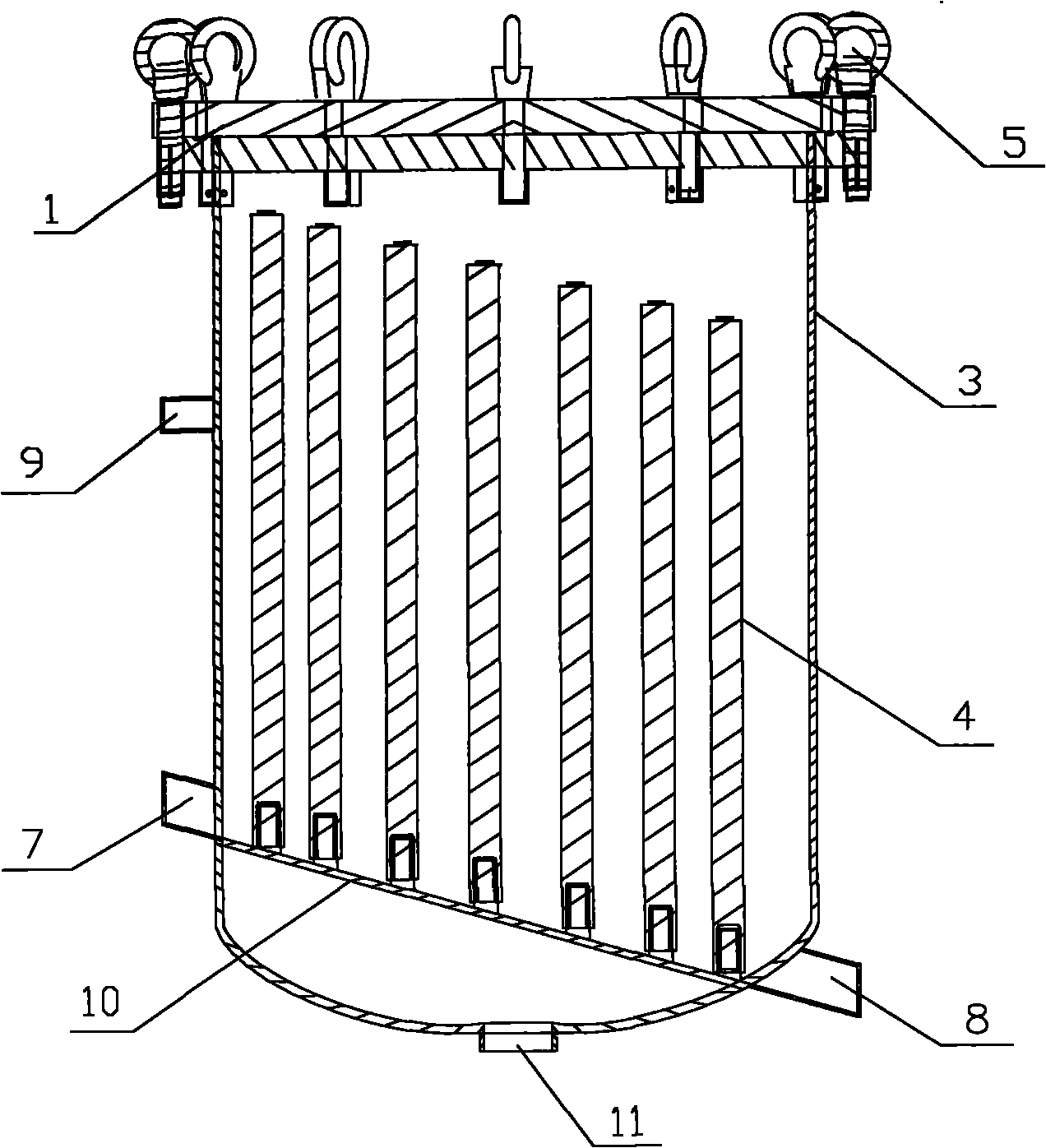
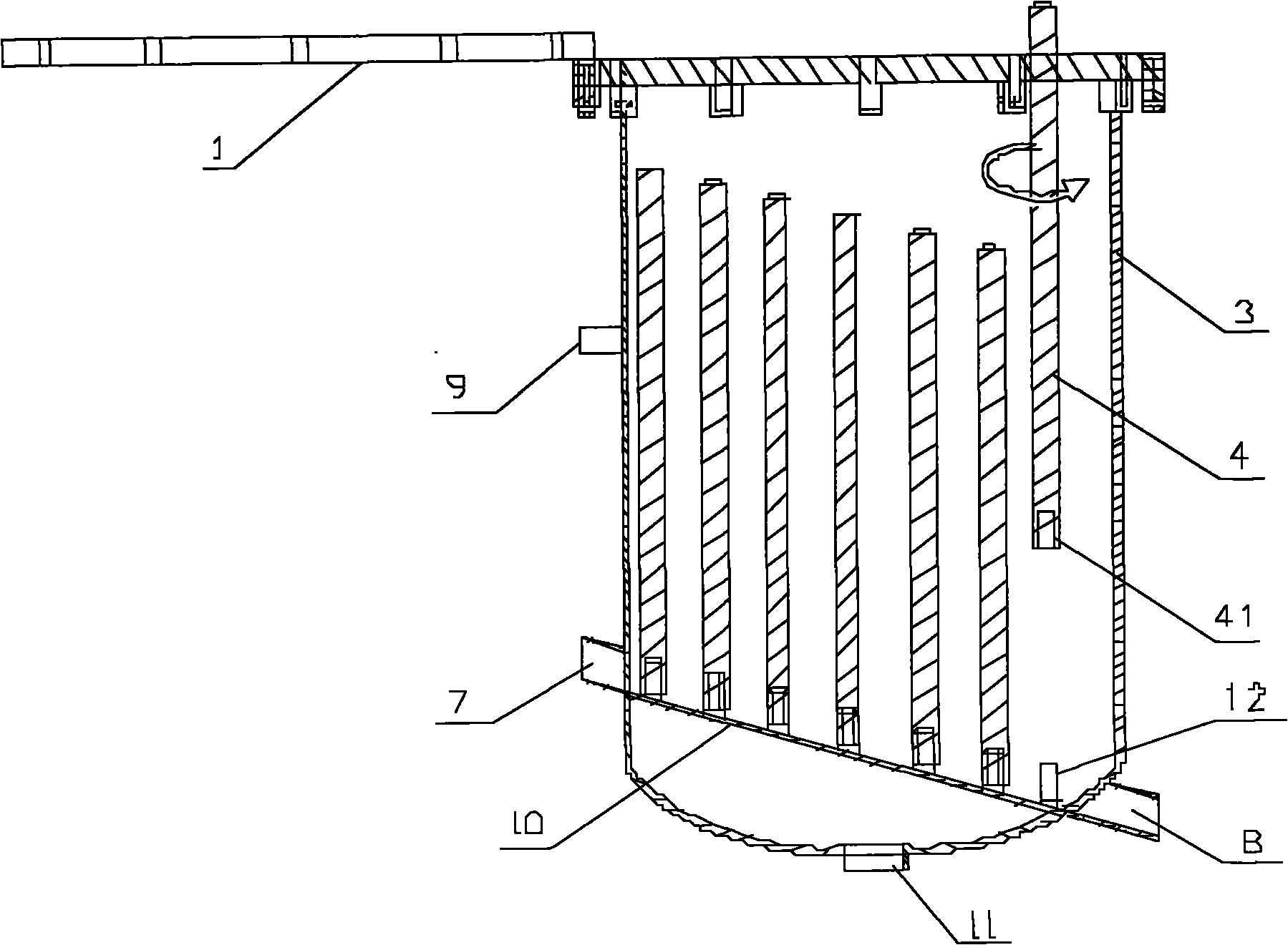
[0021] refer to figure 2 , the filter bucket includes a bucket body 3 and a bucket cover 1, and the bucket body cavity is divided into an upper cavity and a lower cavity by a partition (flange) 10 arranged at the bottom of the bucket body cavity, and the lower cavity is connected with the set The clean oil outlet 11 in the lower part of the barrel body is connected, and the upper cavity is respectively connected with the dirty oil inlet 7 and the dirt outlet 8 arranged on the barrel body. An opening is provided on the end surface, and the opening communicates with the lower cavity.

[0022] Preferably, the bung 1 adopts a plane cover plate, and the plane cover plate is fixedly connected with the bucket body through a plurality of fastening bolts 5 vertically passing through the plane cover plate and the peripheral ...


PUM


Abstract

The invention relates to an improved structure of a filter vat. The filter vat comprises a vat body, a vat cover and a filter element; an inner cavity of the vat body is separated into an upper cavity and a lower cavity by a clapboard arranged on the lower part of the inner cavity of the vat body; the lower cavity is communicated with a clean oil outlet formed on the lower part of the vat body; the upper cavity is respectively communicated with a dirty oil inlet and a dirt outlet which are formed on the vat body; the lower end of the filter element is connected with the clapboard through a thread fastening mechanism; and the lower end face of the filter element is provided with an opening part communicated with the lower cavity. The filter vat is simple in structure, is assembled and maintained without matching of hoisting equipment and a plurality of operators, is time-saving, labor-saving, high-efficiency, quick, and low in assembly and maintenance cost, and cannot make the dirty oil and dirt scatter outside the filter vat so as to avoid polluting the ambient environment.

Description

technical field [0001] The invention relates to a filtering device for filtering waste water, dirty oil and other liquids, in particular to a filtering bucket with an improved structure. Background technique [0002] refer to figure 1 , the common filter barrel is mainly composed of a split design barrel cover 1, flange plate 2 and barrel body 3', the barrel cover and the flange plate are fixedly connected by bolts 5, the upper part of the filter element 4' passes through the flange plate vertically, and The nut screwed on the upper end of the filter element is fixedly connected with the flange. When the filter barrel is maintained, the screw on the barrel cover must be disassembled first, the barrel cover and the flange plate are hoisted in turn with lifting equipment, and then the nuts fixed on the upper end of the filter element are disassembled one by one, so that the filter element can be taken out. , the assembly and disassembly operation of the filter barrel is extr...

Claims


Application Information

Patent Timeline
Patent Type & Authority Applications(China)
IPC IPC(8): B01D29/52B01D29/96B01D35/30
Inventor 郑添全
Owner 江苏福斯利特环保科技有限公司
Why Eureka
Try Eureka