Laser type light guide plate carving equipment and using method thereof

A technology of engraving equipment and light guide plates, applied in laser welding equipment, welding equipment, metal processing equipment, etc., can solve problems such as poor stability and uniformity, inability to produce light guide plates, and easy aging, and achieve high production efficiency.

Inactive Publication Date: 2011-09-14
UNIV OF SHANGHAI FOR SCI & TECH
View PDF6 Cites 11 Cited by
  • Summary
  • Abstract
  • Description
  • Claims
  • Application Information

AI Technical Summary

Problems solved by technology

[0006] Disadvantages: Different sizes require different stencils, and the stencils must be successful once, otherwise they will be scrapped, and the refraction effect on light is worse than that of non-printed ones, that is, the brightness is low; chemical inks are greatly affected by the environment, and are prone to aging and yellowing; The existing printing production process has poor stability and uniformity
[0010] Dis...

Method used


Image

  • Laser type light guide plate carving equipment and using method thereof
  • Laser type light guide plate carving equipment and using method thereof
  • Laser type light guide plate carving equipment and using method thereof

Examples


Embodiment Construction

[0031] In order to make the technical means, creative features, goals and effects achieved by the present invention easy to understand, the present invention will be further described below in conjunction with specific diagrams.

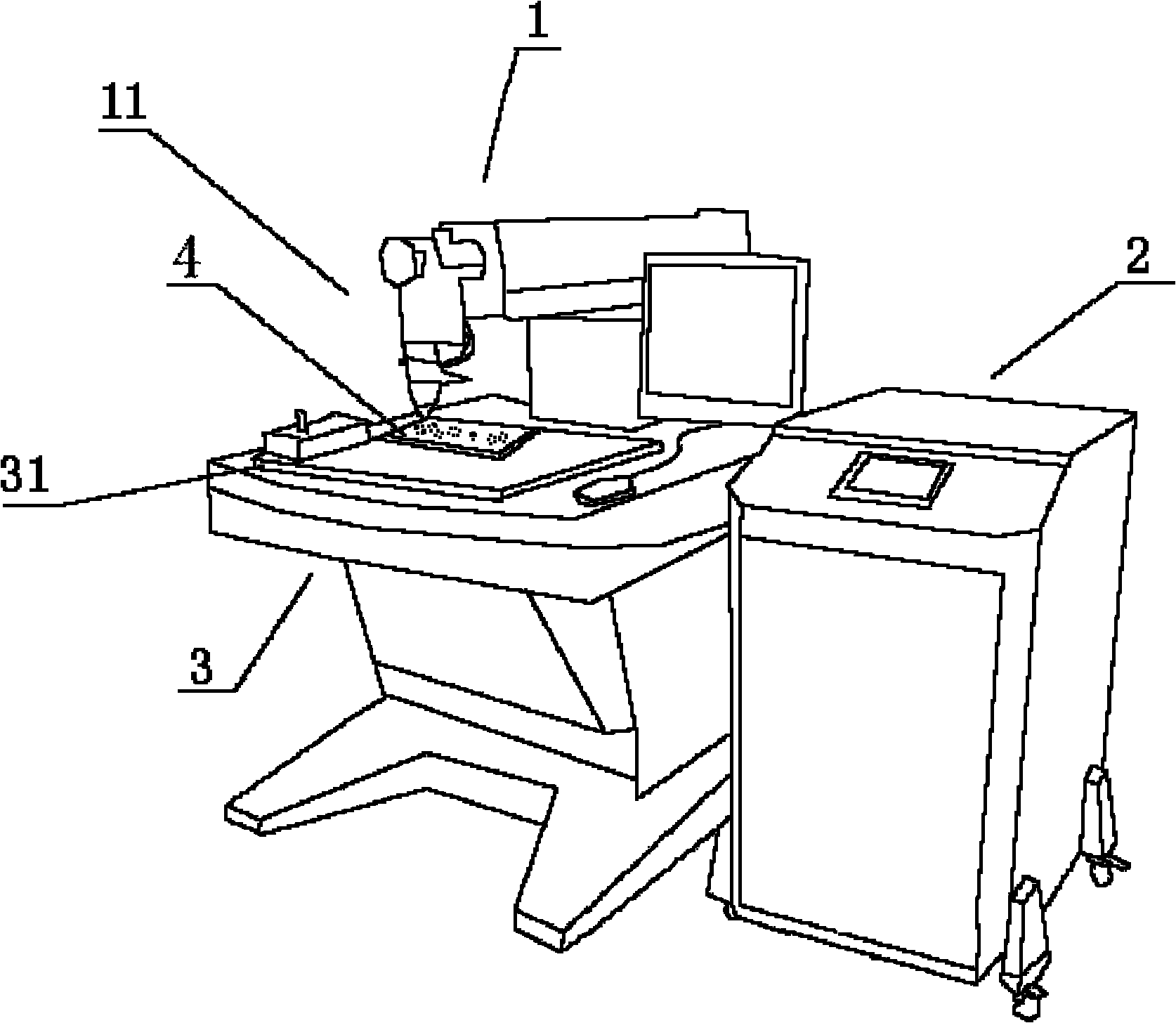
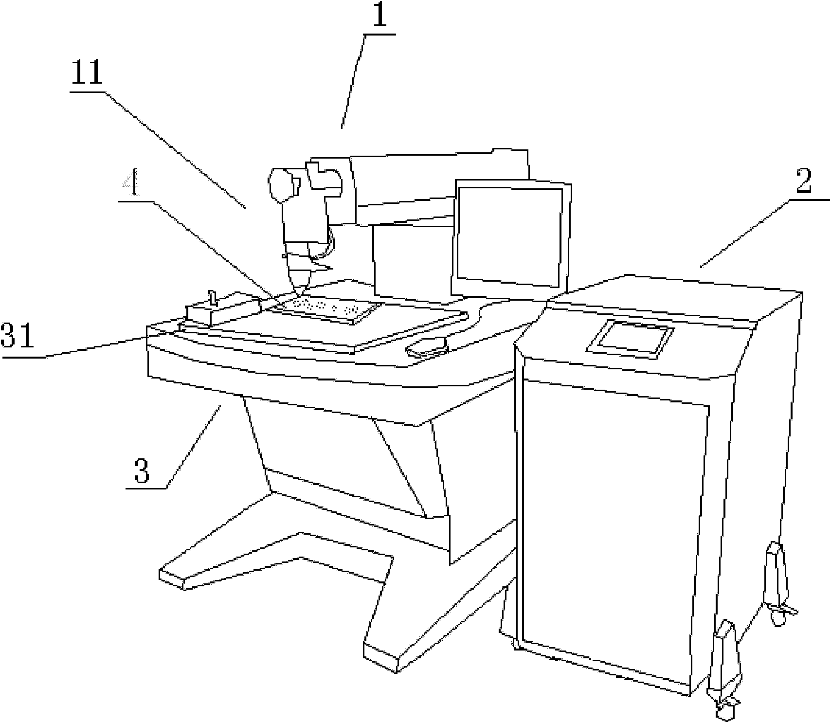
[0032] refer to figure 1 , figure 2 , The laser engraving equipment for the light guide plate includes a laser system 1 and a control system 2 for controlling. The laser system 1 includes a laser 11 and a laser control system 12 . The laser system 1 also includes a vibrating mirror for adjusting the direction of laser emission. The vibrating mirror is located in front of the initial laser emission direction of the laser 11, and the vibrating mirror is connected with a vibrating mirror driving mechanism that drives the vibrating mirror, and the vibrating mirror driving mechanism is controlled by the control system 2 . It also includes a workbench 3, which is provided with a work surface 31 for carrying the light guide plate 4 to be processed. The ...


PUM


Abstract

The invention discloses laser type light guide plate carving equipment and a using method thereof, and relates to the field of production of optical parts. The laser type light guide plate carving equipment comprise a laser device system, a control system with a control function and an operating platform, wherein the laser device system comprises a laser device, a laser device control system and a vibration mirror which is used for adjusting the transmitting direction of laser; the vibration mirror is connected with a vibration mirror driving mechanism which is used for driving the vibration mirror to operate; the vibration mirror driving mechanism is controlled by the control system; an operating surface which is used for bearing a light guide plate to be machined is arranged on the operating platform, and is connected with an operating surface driving mechanism which is used for driving the operating surface to move; the operating surface driving mechanism is controlled by the control system; and the focusing position of the laser device is set inside or on the surface of the light guide plate, and a diffusion groove or a diffusion point is carved inside or on the surface of the light guide plate. In the invention, all molds are not needed; the equipment is suitable for manufacturing light guide plates of various dimensions, is completely operated by computer numerical control during machining, has high production efficiency, can be used for light guide plates in abnormal shapes and can be used for carving the inside or the surface of the light guide plate.

Description

technical field [0001] The invention relates to the field of optical component production, in particular to light guide plate production equipment. Background technique [0002] The existing light guide plate and its preparation technology are classified as follows: [0003] (1) Printing type: [0004] Preparation method: After the shape processing of the acrylic sheet is completed, the light guide dots are printed on the surface by screen printing, and the direction of the light entering from the side is changed into a flat light. [0005] Advantages: The production process is simple and easy to master, the investment is small, and the production cost is low. [0006] Disadvantages: Different sizes require different stencils, and the stencils must be successful once, otherwise they will be scrapped, and the refraction effect on light is worse than that of non-printed ones, that is, the brightness is low; chemical inks are greatly affected by the environment, and are prone...

Claims


Application Information

Patent Timeline
IPC IPC(8): B23K26/36B23K26/02G02B6/00B23K26/042B23K26/362
Inventor 杨波程抒一窦晓鸣倪一李振清张薇
Owner UNIV OF SHANGHAI FOR SCI & TECH
Why Eureka
Try Eureka