Variable speed scooter
A scooter and body technology, which is applied in vehicle gearboxes, vehicle components, chain/belt transmissions, etc., can solve problems such as large movement angle, difficulty in going uphill, and large pedaling force, so as to meet the requirements of uphill power and flat speed The effect of fast and simple speed change process
- Summary
- Abstract
- Description
- Claims
- Application Information
AI Technical Summary
Problems solved by technology
Method used
Image
Examples
Embodiment 1
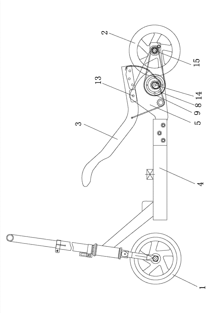
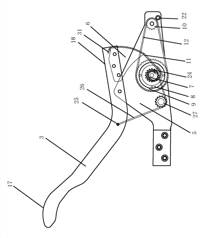
[0075] See figure 1 and figure 2 , a variable speed scooter, comprising a vehicle body, a front wheel 1, a rear wheel 2 and a drive system, the vehicle body includes a power lever 3 and a body bracket, the body bracket includes a main bracket 4 and a power fixing piece 5, and the power fixing piece 5 is provided with an upper power The rotating shaft 13 , the front power rotating shaft 14 and the rear power rotating shaft 15 , and the power lever 3 are arranged on the upper power rotating shaft 13 . This embodiment is a single power output structure, the number of the drive system is one, the number of the power lever 3 is one, the drive system is arranged on the right side of the vehicle body support, the drive system is connected to the power lever 3, and the power lever 3 is from opening to closing , has a power output; the power lever 3 returns from closing to opening, and has no power output.
[0076] The drive system includes a power system and a return system. The po...
Embodiment 2
[0093] The difference between this embodiment and Embodiment 1 is that this embodiment adopts a return system of another structure, the return system includes a return gear 24 and a return spring 28, and the return gear 24 is sleeved on the front One end of the power shaft 14 and the return spring 28 are fixed to the main bracket 4 , and the other end of the return spring 28 is connected to the return gear 24 through the return chain 26 . Such as Figure 18 As shown, when the power lever 3 is in the open state, the return spring 28 is in the pre-tension state, and when the front end stepping point 17 of the power lever 3 is stepped down, the sprocket 6 moves upward, and the eccentric is pulled by the sprocket chain 11 The wheel 7 turns counterclockwise, and since the eccentric wheel 7 and the return gear 24 both fix the front power rotating shaft 14, the return gear 24 also rotates counterclockwise with it, thereby pulling the return chain 26, so that the return spring 28 is o...
Embodiment 3
[0095] Such as Figure 19 and Figure 20 , this structure is one of the dual power output structures. The number of drive systems in this embodiment is two, and the number of power levers 3 is two. The two drive systems are respectively arranged on the left and right sides of the vehicle body bracket. The drive system on the side is connected to the power lever 3 on the left side, and the drive system on the right side is connected to the power lever 3 on the right side. In this embodiment, the power lever 3 on the left side and the power lever 3 on the right side rotate alternately around the power shaft 13 at the same time, and only two feet need to be placed on the front end stepping point 17 of the power lever 3 on the left side and on the right side respectively. Stepping on the front end stepping point 17 of the power lever 3 of the power lever 3 on the left side and the power lever 3 on the right side move up and down, so that the left and right power systems are in th...
PUM
 Abstract
Description
Claims
Application Information
 - R&D
- Intellectual Property
- Life Sciences
- Materials
- Tech Scout
- Unparalleled Data Quality
- Higher Quality Content
- 60% Fewer Hallucinations
Browse by: Latest US Patents, China's latest patents, Technical Efficacy Thesaurus, Application Domain, Technology Topic, Popular Technical Reports.
© 2025 PatSnap. All rights reserved.Legal|Privacy policy|Modern Slavery Act Transparency Statement|Sitemap|About US| Contact US: help@patsnap.com


