Duct aerofoil system and aerial craft applying duct aerofoil system

An aircraft and wing technology, applied in the field of aircraft, can solve problems such as limited lift, inability to take off and land vertically, and heavy weight, and achieve the effect of smooth transition

Inactive Publication Date: 2011-09-14
龙川
View PDF6 Cites 17 Cited by
  • Summary
  • Abstract
  • Description
  • Claims
  • Application Information

AI Technical Summary

Problems solved by technology

In this way, after the engine is started, the groove will effectively limit the slipstream formed behind the engine propeller, and generate a large suction force in the groove area to obtain a large lift. However, the grooved wing aircraft can only take off and land at a short distance, not vertically. ups and downs
[0003] American Muller designed and manufactured the m400 in the 1990s. The m400 has four ducted fans arranged symmetrically on both sides of the aircraft fuselage. The ducted shell gradually transitions from a circular shape at the front edge to a rectangular shape at the rear edge. And the rectangle at the rear edge is inclined backward from bottom to top, and louver-type guide vanes are arranged in parallel. When the ducted fan is tilted to an inclined angle, the slip flow of the fan passing through the louver-type guide vanes is ejected downward, generating an upward flow. The force makes the aircraft rise vertically. Muller hopes that the ducted shell can generate lift to maintain the horizontal flight of the aircraft after gradually tilting the ducted fan to a horizontal state. However, the lift generated by his ordinary shaped ducted shell is limited and cannot Maintain the level flight of the aircraft, and the tilting mechanism is complicated and heavy
[0004] The Breguet 941 produced by the French Breguet company in the 1960s used the lift flap technology to deflect the propeller slipstream with a larger flap, so that the slipstream deflected downward to generate upward lift. The lift generated on the wings enables the aircraft to take off and land short distances, but this aircraft cannot take off and land vertically

Method used


Image

  • Duct aerofoil system and aerial craft applying duct aerofoil system
  • Duct aerofoil system and aerial craft applying duct aerofoil system
  • Duct aerofoil system and aerial craft applying duct aerofoil system

Examples


Embodiment 1

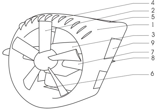
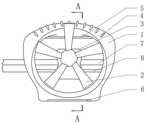
[0043] Embodiment 1: The aircraft has two ducted wing systems, and the two ducted wing systems are symmetrically arranged on both sides of the rear part of the fuselage 12 of the aircraft.

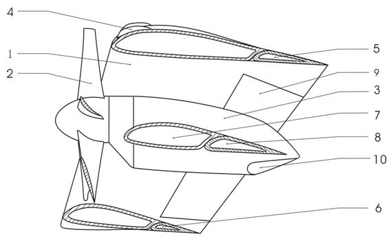
[0044] The specific installation method of the ducted wing system is: the extended section of the support wing 7 outside the ducted wing is connected with the back of the fuselage 12, and the ducted wing 1 is connected to the side below the side of the fuselage 12. There are inclined support wings 11 to support the angle, and the other end of the inclined support wings 11 is installed on the bulge on the side of the fuselage 12; there is a transmission shaft connection between the ducted wing fans 2 on both sides, so that the fans 2 on both sides can always maintain The same rotating speed; the ducted wing system on both sides of the aircraft has a dihedral angle, so that the aircraft has lateral stability when it takes off and lands vertically, hovers, advances at low speed, and flies hori...

Embodiment 2

[0051] Embodiment 2: The ducted wing system is one and the fuselage is used as the fan shaft to be arranged at the rear of the aircraft. Other structures of the aircraft are the same as in Embodiment 1, so that the volume of the aircraft is smaller.

Embodiment 3

[0052] Embodiment 3: There are four ducted wing systems, which are symmetrically arranged on both sides of the aircraft fuselage. The aircraft adopts a canard layout or a tandem wing layout, and there is no built-in ducted fan in the nose of the aircraft.

[0053] The two aircraft described in the second embodiment and the third embodiment can also realize vertical take-off and landing, horizontal flight, and smooth transition between the vertical take-off and landing and the horizontal flight state.

[0054]The inclined shape can also not be adopted between the upper part and the lower part of the leading edge of the ducted wing, and other structures are the same as in the embodiment, so that the fan of the ducted wing system can also accelerate the inner wall surface of the lower part of the ducted wing The airflow, and the airflow on the inner and outer walls of the upper half of the ducted wing can be accelerated, so that the ducted wing can generate a lot of lift, but if i...


PUM


Abstract

The invention discloses a duct aerofoil system which comprises a duct aerofoil and a fan arranged on the front edge of the duct aerofoil. The duct aerofoil has an annular structure; a longitudinal cross section of the duct aerofoil is in an airfoil shape; when fan blades rotate to the lower half part of the duct aerofoil, blade tips of the fan blades are higher than the front edge of the lower half part of the duct aerofoil; when the fan blades rotate to the upper half part of the duct aerofoil, the fan blades are positioned in an outer space of the upper half part of the duct aerofoil; and the blade tips of the fan blades are higher than the outer wall of the front edge part of the upper half part of the duct aerofoil. The fan of the duct aerofoil system can simultaneously accelerate theair flow on the surface of the inner wall of the lower half part of the duct aerofoil of the annular structure and the air flow on the surfaces of the inner wall and the outer wall of the upper half part so as to generate a huge lifting force; high lift devices such as flap on the back edge of the duct aerofoil and the like downwards deflect so that the slip flow of the fan can be spurted backwards and a frontward-upward pushing force is generated; an aerial craft applying the duct aerofoil system can achieve vertical rise and fall, horizontal flying, and the stable transition between a vertical rise and fall state and a horizontal flying state.

Description

technical field [0001] The invention relates to a wing, in particular to a ducted wing system and an aircraft using the ducted wing system. Background technique [0002] American Custer designed and manufactured the grooved wing aircraft in the 1940s, which is an ultra-short take-off and landing aircraft that obtains high lift by actively accelerating the airflow. The concept of the grooved wing is to actively accelerate the grooved aircraft The airflow on the upper surface of the wing obtains lift instead of passing through the airflow like conventional aircraft wings. The wing of this aircraft is designed in the shape of a semicircular groove that is curved downward in the part adjacent to the fuselage, and the engine is placed in the semicircular depression. In this way, after the engine is started, the groove will effectively limit the slipstream formed behind the engine propeller, and generate a large suction force in the groove area to obtain a large lift. However, th...

Claims


Application Information

Patent Timeline
Patent Type & Authority Applications(China)
IPC IPC(8): B64C3/58B64C9/02
Inventor 龙川
Owner 龙川
Why Eureka
Try Eureka