
Fuel injection system

A technology of injection system and fuel oil, applied in combustion engines, internal combustion piston engines, hoses, etc., can solve the problems of complicated, troublesome and rusty installation of grounding wires, and achieve the effect of improving the reliability of electrical connections

Active Publication Date: 2011-09-14
TOYODA GOSEI CO LTD
View PDF5 Cites 7 Cited by
  • Summary
  • Abstract
  • Description
  • Claims
  • Application Information

AI Technical Summary

Problems solved by technology

However, in this conventional structure, the installation work of the ground wire is complicated and cumbersome
In addition, due to the use of metal terminals, there will be problems with rusting

Method used


Image

  • Fuel injection system
  • Fuel injection system
  • Fuel injection system

Examples


Embodiment Construction

[0025] (1) Schematic structure of fuel injection system FS

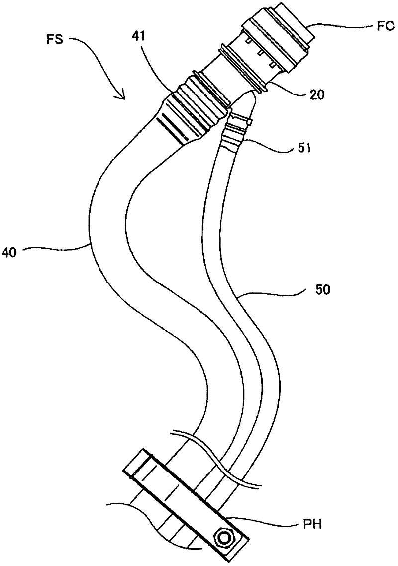
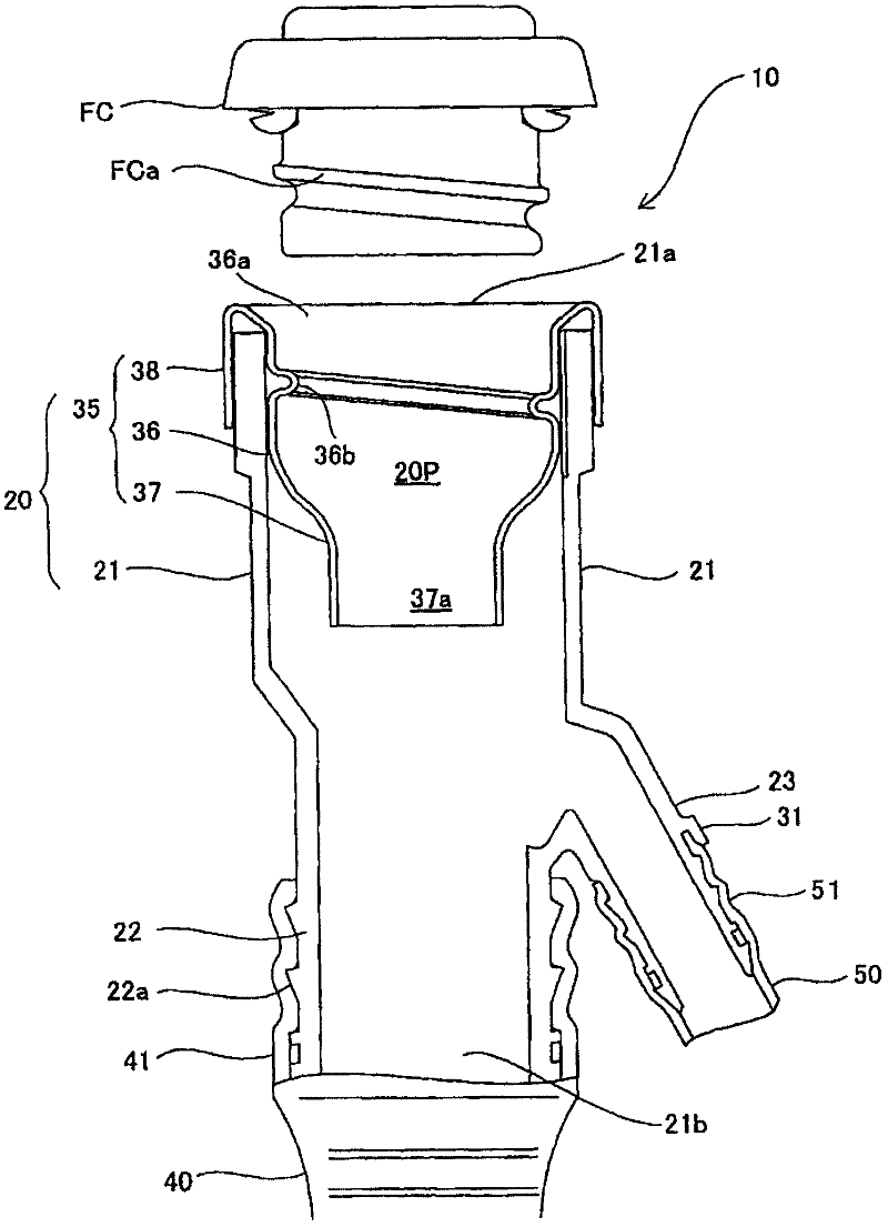
[0026] figure 1 It is a schematic structural diagram showing a fuel injection system for injecting fuel into a fuel tank according to an embodiment of the present invention. The fuel injection system FS is used to inject fuel into the fuel tank of a motor vehicle, and includes: a fuel tank cap FC; a fuel filler 20; a fuel pipe 40, 50 connected to the fuel filler 20; 40, 50 are fixed to the body side parts (not shown in the figure); and, fuel tank connectors (not shown), which are used to connect the ends of the fuel pipes 40, 50 to the fuel tank. The fuel pipe 40 is a resin pipe, formed of polyethylene, which connects the filler port 20 to the fuel tank. One end of the fuel pipe 40 is configured to be suitable for connecting to the pipe joint end 41 of the filler port 20, while the other end thereof is connected to a fuel tank connector, which is welded together with the fuel tank. The fuel pipe 50 is a vent pipe ...


PUM


Abstract

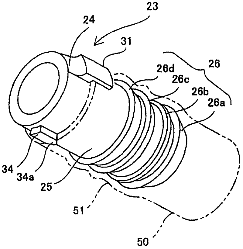
The invention discloses a fuel injection system (FS), which comprises an oiling port (20), a pipe joint part (23) and a fuel pipe (50) equipped with a conductive layer for being connected with the pipe joint part (23). The pipe joint part comprises a connection body (25), a disengaging protruding part (26) connected with the outer circumferential surface of the connection body (25) so as to be ring-shaped with the external diameter thereof greater than the inner diameter of the fuel pipe and a grounding connection part (31). The grounding connection part equipped with a fastening part (32) isarranged on the outer circumferential surface of the connection body so as to be protruded with an L-shaped cross-section thereof. An insertion gap (31s) is between the grounding connection part and the outer circumferential surface of the connection body is defined. The fastening part (32) is equipped with a connection protruding part (32b). The end portion of the pipe joint end (51) is allowed to pass through the disengaging protruding part (26). The pipe joint end (51) is pressed to be arranged on the connection body (25) so as to be fit into the insertion gap. Therefore, the connection protruding part is electrically connected with the external layer of the pipe joint end.

Description

technical field [0001] The present invention relates to a fuel injection system for injecting fuel into a fuel tank of a motor vehicle, etc., and more particularly, the present invention relates to grounding the human body using a conductive part of the motor vehicle so that when opening or closing the fuel tank cap (fuel cap) Filler cap) can achieve the purpose of releasing the static electricity charged by the human body through the fuel pipe. Background technique [0002] Generally, as this type of fuel injection system, there is known a mechanism in which fuel is injected into a fuel tank through a resin fuel pipe connected to a filler neck. In such a mechanism, there is a need for a mechanism that provides grounding for the human body that operates the fuel tank, and discharges the static electricity carried by the human body to the side of the vehicle body through the conductive components arranged on the vehicle body, so as to avoid the operator holding the fuel tank ...

Claims


Application Information

Patent Timeline
Patent Type & Authority Applications(China)
IPC IPC(8): B67D7/54F16L11/127
CPCY02T10/123Y02T10/12
Inventor 关原敦史加藤哲史三吉启司平松义也
Owner TOYODA GOSEI CO LTD
Learn More