Method and system for controlling power matching of mobile working machine

A technology of mobile operation and control method, which is applied in the direction of fluid pressure actuation system components, mechanical equipment, fluid pressure actuation devices, etc., and can solve problems such as different pressure loss and hydraulic pressure loss

Inactive Publication Date: 2011-09-14
JIANGSU LIUGONG MACHINERY +1
View PDF5 Cites 19 Cited by
  • Summary
  • Abstract
  • Description
  • Claims
  • Application Information

AI Technical Summary

Problems solved by technology

The traditional hydraulic system uses a quantitative pump to supply oil to each hydraulic component. For different working conditions, the required hydraulic oil flow rate is also different. The usual practice is to let the excess hydraulic oil flow back to the hydraulic oil tank through the overflow valve, resulting in redundant hydraulic energy is lost in the overflow process

Method used


Image

  • Method and system for controlling power matching of mobile working machine
  • Method and system for controlling power matching of mobile working machine
  • Method and system for controlling power matching of mobile working machine

Examples


Embodiment 1

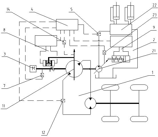
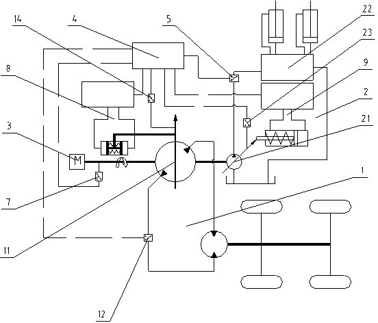
[0020] Embodiment 1: as figure 1 As shown, the power distribution control system of the mobile working machine includes a traveling hydraulic system 1, a working hydraulic system 2 and an engine system 3. The traveling hydraulic system 1 includes a traveling pump 11, and the working hydraulic system 2 includes a working pump 21. The traveling pump 11 And the working pump 21 is connected with the engine system 3 , therefore, the traveling pump 11 and the working pump 21 are kept in linkage with the engine system 3 . The power distribution control system also includes pressure sensors 5, 12 for measuring the pressure of the working hydraulic system 2 and the traveling hydraulic system 1, a speed sensor 7 for measuring the engine speed, detecting the working pump 21 of the working hydraulic system 2 and the traveling pump 11 of the traveling hydraulic system 1 Displacement sensors 23, 14 of the displacement, a controller 4 that receives the signals of the displacement sensors 23,...

Embodiment 2

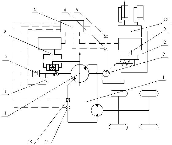
[0025] Embodiment 2: as figure 2 As shown, the power distribution control system of the mobile working machine includes a traveling hydraulic system 1, a working hydraulic system 2 and an engine system 3. The traveling hydraulic system 1 includes a traveling pump 11, and the working hydraulic system 2 includes a working pump 21. The traveling pump 11 And the working pump 21 is connected with the engine system 3 , therefore, the traveling pump 11 and the working pump 21 are kept in linkage with the engine system 3 . The power distribution control system also includes flow sensors 6 and 13 for measuring the flow of the working hydraulic system 2 and the traveling hydraulic system 1, pressure sensors 5 and 12 for measuring the pressure of the working hydraulic system 2 and the traveling hydraulic system 1, and a speed sensor for measuring the engine speed 7. The controller 4 that receives the signals of the flow sensors 6, 13, the pressure sensors 5, 12 and the speed sensor 7, a...


PUM


Abstract

The invention relates a method and a system for controlling power matching of a mobile working machine. The system comprises a travelling hydraulic system, a working hydraulic system, an engine system, a sensor, a pressure sensor, a rotation speed sensor, a controller and a control unit, wherein the travelling hydraulic system and the working hydraulic system are driven by the engine system; the sensor is used for acquiring the flow quantity of the working hydraulic system and the travelling hydraulic system; the pressure sensor is used for measuring the pressure of the working hydraulic system and the travelling hydraulic system; the rotation speed sensor is used for measuring the rotation speed of an engine; the controller is used for receiving signals of all sensors; and the control unit is used for controlling the two hydraulic systems. The controller calculates the power of the two hydraulic systems and the maximum theoretical output power of the engine at a current rotation speed and reasonably allocates power to the engine according to an actual working condition when the sum of the power of the two hydraulic systems reaches the maximum theoretical output power of the engine. By the system for controlling power matching, reasonable power allocation of the two hydraulic systems is ensured, and the engine is prevented from flameout due to overload.

Description

technical field [0001] The invention relates to a mobile operating machine control method and system, in particular to a power matching control method and system for a working hydraulic system and a traveling hydraulic system of a mobile operating machine. Background technique [0002] Traditional mobile working machinery includes two important systems, the working hydraulic system and the traveling hydraulic system, which are generally driven by engines. The power of the hydraulic system is equal to the product of the pressure of the system and the flow rate of the hydraulic oil in the system, while the pressure of the hydraulic system is determined by the load, and the flow rate of the hydraulic oil is equal to the product of the displacement and the rotational speed of the hydraulic pump, so the control hydraulic system mainly It is the control of the displacement and speed of the hydraulic pump. The output power of the engine is equal to the product of the rotational sp...

Claims


Application Information

Patent Timeline
Patent Type & Authority Applications(China)
IPC IPC(8): F15B21/00
Inventor 罗石忠牛宏杰邵年陈晋市杜丹刘昕晖
Owner JIANGSU LIUGONG MACHINERY
Why Eureka
Try Eureka