Distributed light emitting diode (LED) optical fibre coupling lighting car lamp

A fiber-coupled, distributed technology, applied in lighting devices, fixed lighting devices, lighting and heating equipment, etc., can solve problems such as poor heat dissipation, uneven lighting, poor dispersion of LED modules, etc., to achieve good effects and light performance Improved effect

Inactive Publication Date: 2011-09-14
JIANGSU HONGCHANG SCI & TECH +1
View PDF5 Cites 6 Cited by
  • Summary
  • Abstract
  • Description
  • Claims
  • Application Information

AI Technical Summary

Problems solved by technology

[0004] The main problem to be solved by the present invention is: to overcome the problem of poor dispersion and array of existing LED modules, and the problem of uneven illumination. Better uniformize the output light, and through the arrangement of distributed LED module groups, overcome the phenomenon of poor heat dissipation caused by LED array problems

Method used


Image

  • Distributed light emitting diode (LED) optical fibre coupling lighting car lamp
  • Distributed light emitting diode (LED) optical fibre coupling lighting car lamp
  • Distributed light emitting diode (LED) optical fibre coupling lighting car lamp

Examples


Embodiment Construction

[0020] The following are the best embodiments of the present invention, but are not used to limit the present invention.

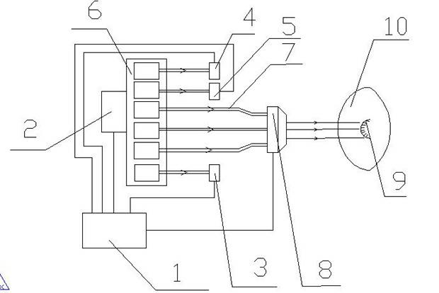
[0021] A preferred embodiment of the present invention includes: a light collecting groove part, a front cover lamp part, a center console control part, an LED module group part, and an LED optical fiber group part.

[0022] The central console 1 controls the working status of the fog lamp LED module 4, the turn signal LED module 5 and the LED module group through the data transmission line. The following focuses on the working status of the central console 1 controlling the headlights.

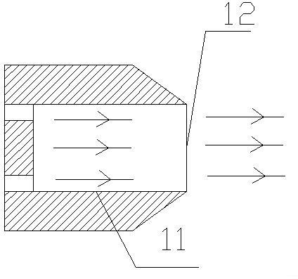
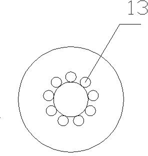
[0023] After the center console 1 supplies power to the LED module power supply 2, the LED module group 6 is in working state, the LED modules in the LED module group 6 emit light, and the light is transmitted to the left end of the light collecting groove 8 through the optical fiber 7 (the structure of the light collecting groove 8 refer to figure 2 , image 3 ), the ...


PUM


Abstract

The invention belongs to the field of light emitting diode (LED) optical fibre lighting car lamps and in particular relates to a distributed LED optical fibre coupling lighting car lamp, which comprises a light collection tank part, a front shade lamp part, a centre console control part, an LED module group part and an LED optical fibre group part. In the invention, the problems of poor radiation and non-uniform lighting of the conventional LED car lamp are solved by distributed layout of the LED module group and moulding of multi-ellipsoid and coons curves of a lamp shade. The distributed LED optical fibre coupling lighting car lamp provided by the invention can uniformly distribute output lights, can better uniformize the output lights and can overcome the defects of the conventional LED.

Description

technical field [0001] The invention relates to the field of optical fiber vehicle lights, in particular to the field of heat dissipation and light effect correction of distributed LED fiber optic coupled lighting vehicle lights. Background technique [0002] The application of optical fiber in the field of lighting is more and more extensive. From the beginning, it was only used to produce special lighting effects (simulating twinkling stars), and now it is not only widely used in decorative lighting, but also in general lighting. Fiber optic lighting has entered the real world. A full range of lighting fields, especially optical fibers can also be used in places where ordinary lighting equipment cannot achieve lighting. Due to the technical progress and cost reduction of fiber optic lighting in terms of versatility and output light intensity, this lighting method has become more and more recognized in the lighting market. Now, fiber optic lighting has shown its superiorit...

Claims


Application Information

Patent Timeline
Patent Type & Authority Applications(China)
IPC IPC(8): F21S8/10F21V8/00F21V7/22F21V19/00F21W101/02F21Y101/02F21W107/10F21Y105/10F21Y115/10
Inventor 崔洪昌任旭东杜正清徐传超张田
Owner JIANGSU HONGCHANG SCI & TECH
Why Eureka
Try Eureka