

Magnet fixing plate and preparation method thereof
A technology of magnet fixing and disc body, applied in the direction of magnetic drive clutch, non-mechanical drive clutch, clutch, etc., can solve the problems of complex fixed permanent magnet process, reduced construction cost of ferrite permanent magnet, etc., and achieve the shape and arrangement of magnetic poles. Flexibility, avoid custom costs, facilitate parts maintenance and replacement
- Summary
- Abstract
- Description
- Claims
- Application Information
AI Technical Summary
Problems solved by technology
Method used
Image

Examples
Embodiment 1
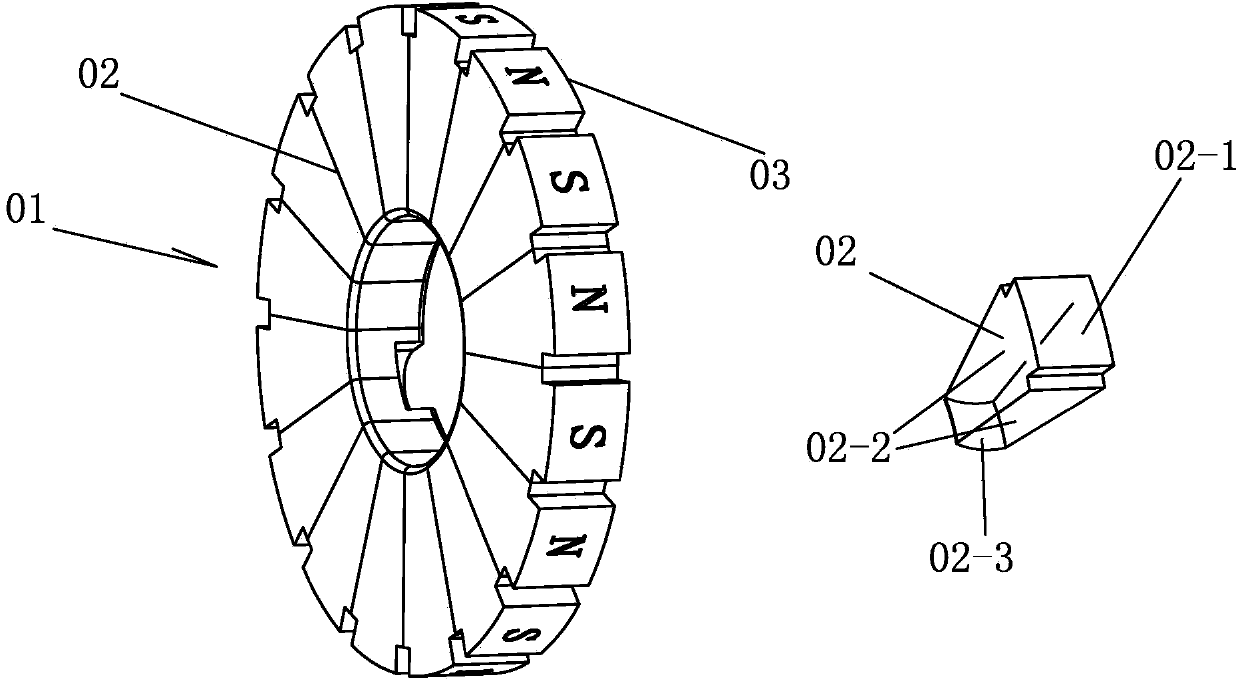
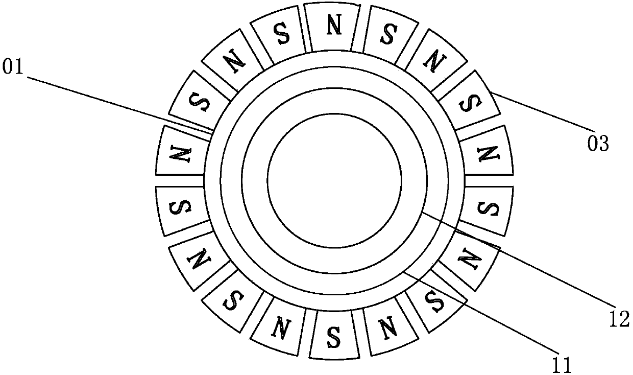
[0043] Such as figure 1 As shown, the disc body 01 is formed by sequentially connecting several fan-shaped plates 02 with the same central angle in the circumferential direction, and a through hole is opened in the center of the disc body 01, so that each fan-shaped plate 02 includes a peripheral arc-shaped side wall 02-1 , an inner peripheral arc-shaped side wall 02-3 and two radial side walls 02-2 connecting the end lines of the same-side arc-shaped side wall, each fan-shaped plate is provided with a boss 03 on the outer peripheral arc-shaped side wall, adjacent Grooves are formed between the bosses 03 . The boss 03 is a cylinder, the axis of the cylinder is parallel to the axis of the disk, and the horizontal cross-section of the cylinder is rectangular, almost circular, triangular or trapezoidal.
[0044] The fan-shaped plate 02 and the boss 03 are made of ferrite material powder sintered or bonded, and the fan-shaped plate 02 is radially magnetized by a pulse magnetizer,...
Embodiment 2
[0053] Use a whole piece of ferrite to process the disk body 01 described in Example 1, open a central through hole with the center of the disk body 01 as the center, and process evenly spaced bosses on the circumferential side wall of the disk body 01 03. Use a pulse magnetizer to magnetize each boss 03 on the disk body 01 in the axial direction, and the adjacent bosses 03 have opposite polarities.
[0054] In the above embodiment, the specific method for axially magnetizing the boss 03 is as follows:
[0055] Such as Figure 11 As shown, the width of the sleeve 13 along the radial direction of the disk body 01 is less than or equal to half of the width of the boss 03 in the corresponding direction (in order to expose the boss 03 as much as possible after the sleeve is put on), the sleeve 13 is Fixing bolts 13-1 are respectively arranged on the two end faces of the body 01 in the axial direction near the center axis of the disc body, and the sleeve 13 is located at the edges...
Embodiment 3
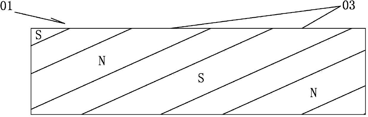
[0064] Such as image 3 Shown is a schematic diagram of the expansion of the outer peripheral arc-shaped side wall of the magnet fixed disk. The boss 03 is a rectangular strip with a high aspect ratio. On the outer peripheral arc-shaped side wall, adjacent rectangular strips 03 are parallel to each other, and the magnetic poles are opposite. The long side of the strip 04 forms an included angle of 55-70 degrees with the axis of the disc body. The horizontal section shape of the rectangular strip is rectangle, quasi-circle, triangle or trapezoid.
[0065] Utilizing the winding length of the rectangular strip on the outer peripheral arc-shaped side wall, the two ends of a rectangular strip and two adjacent rectangular strips can generate magnetic force lines to attract each other, forming a continuous magnetic force line package around the outer peripheral arc-shaped side wall Network, increase the magnetic flux intensity.
[0066] In the above embodiment, the same magnetizati...
PUM
| Property | Measurement | Unit |
|---|---|---|
| Thickness | aaaaa | aaaaa |
| Diameter | aaaaa | aaaaa |
Abstract
Description
Claims
Application Information