Battery diagnosis device and method
A battery and resistor technology, applied in the field of battery diagnostic devices and methods, capable of solving unreliable and other problems
- Summary
- Abstract
- Description
- Claims
- Application Information
AI Technical Summary
Problems solved by technology
Method used
Image
Examples
no. 2 example
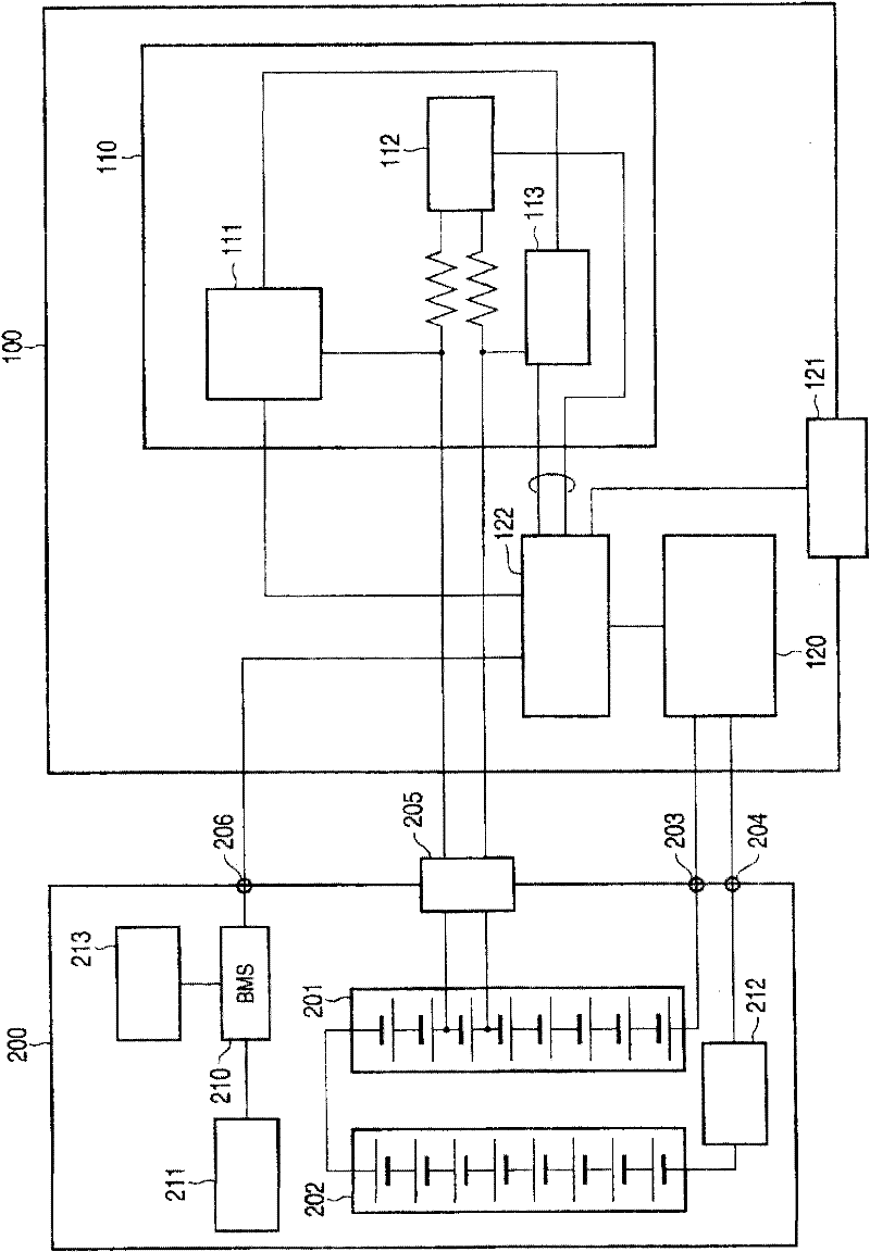
[0090] The second embodiment differs from the first in that the current value of the battery is calculated using the measured current capacity and the measured R SOL with R CT to be sure. Therefore, the same components as those of the first embodiment are denoted by the same reference numerals used in the first embodiment, and their detailed explanations are omitted here.
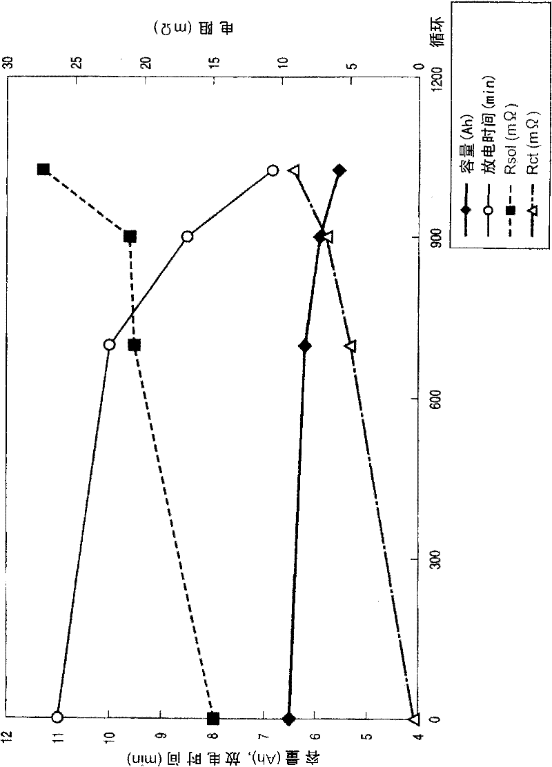
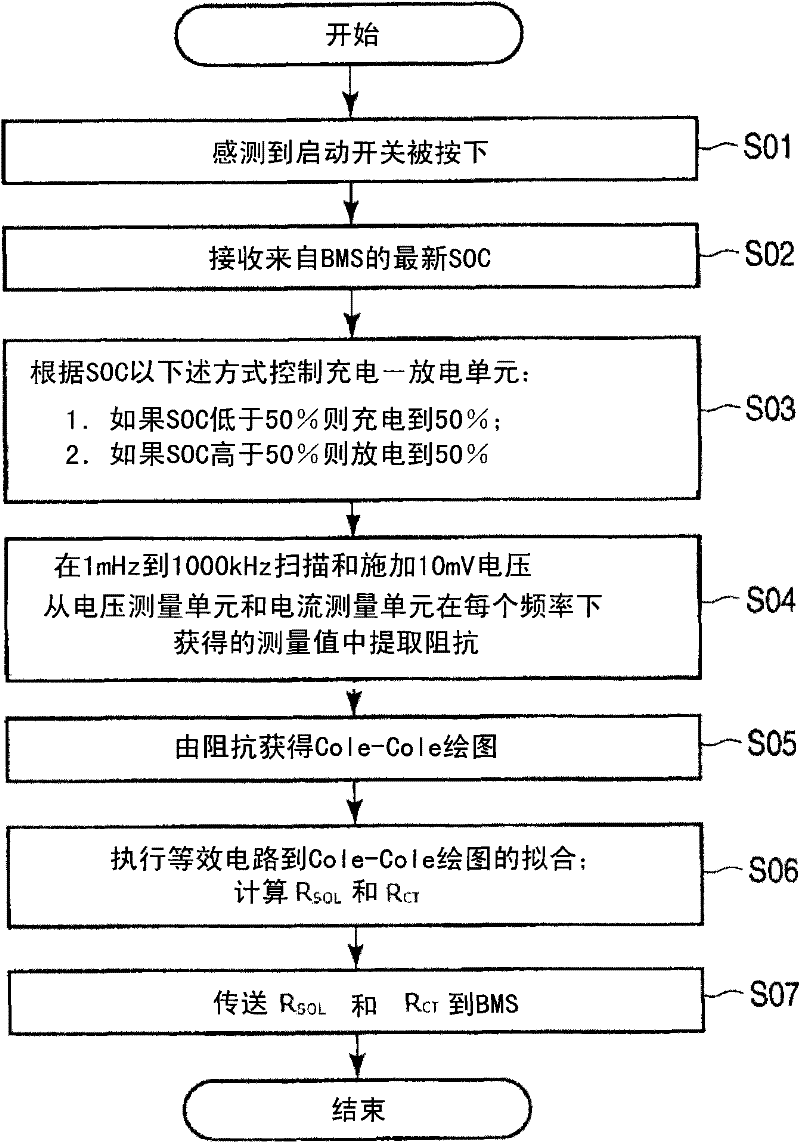
[0091] In the second embodiment, in periodic diagnosis of an electric vehicle or the like, R is measured when the battery pack 200 is connected to the diagnosis device 100 SOL with R CT , as described in the first embodiment.
[0092] Next, the battery capacity at different C rates was measured.
[0093] The charging-discharging unit 120 of the diagnostic device 100 has a function of performing step-down discharge and step-down charging, and is capable of measuring battery capacities at various C rates: 1C, 2C, 4C, and 8C.
[0094] Figure 8 is a flow chart showing the outline of the operation to dete...
no. 3 example
[0119] In the second embodiment, charging and discharging operations are controlled by the charging-discharging unit 120 to measure the battery capacities of the respective currents of 1C, 2C, 4C, and 8C. The third embodiment differs from the second embodiment in that the index is measured only by the charging operation. Therefore, the same components as in the first embodiment are denoted by the same reference numerals as in the first embodiment, and their detailed explanations are omitted here.
[0120] Figure 14 The relationship between the time TH4 obtained by charging and the time TH1 is shown. refer to Figure 14 , describing the operation of the controller 122.
[0121] The diagnostic device 100 is connected to the battery pack 200, the controller 122 is switched to a mode for controlling charging, and the start switch 121 is turned on. The controller 122 then controls the charging-discharging unit 120 to perform 8C charging. When sensing that the total voltage of...
PUM
 Abstract
Description
Claims
Application Information
 - R&D
- Intellectual Property
- Life Sciences
- Materials
- Tech Scout
- Unparalleled Data Quality
- Higher Quality Content
- 60% Fewer Hallucinations
Browse by: Latest US Patents, China's latest patents, Technical Efficacy Thesaurus, Application Domain, Technology Topic, Popular Technical Reports.
© 2025 PatSnap. All rights reserved.Legal|Privacy policy|Modern Slavery Act Transparency Statement|Sitemap|About US| Contact US: help@patsnap.com


