Multi-functional toll collection lane controlling and managing system of toll road

A multi-functional, lane-based technology, applied in the direction of instruments, ticketing equipment, etc., can solve the problems of reducing the traffic capacity of toll stations, consuming a lot of money and manpower, material resources, and few users, so as to achieve faster traffic capacity and high intelligence performance effect

Inactive Publication Date: 2011-09-14
王铁中
View PDF8 Cites 36 Cited by
  • Summary
  • Abstract
  • Description
  • Claims
  • Application Information

AI Technical Summary

Problems solved by technology

It is understood that there are not many stations where ETC lanes are installed (only less than 20 of the 150 toll stations in Jiangxi Province are installed), and there are few ETC exit and entrance lanes, etc., resulting in very few users, which makes the ETC Convenience functions do not show what they should do
For example, fully automatic toll collection is implemented at all existing toll stations (ETC can only be installed with more than six lanes). Since most toll stations in our province have less than five lanes, and some have only two lanes (one entry and one exit), special ETC for expansion If there is no channel, it is necessary to demolish and requisition land, which will not only waste precious land resources, but also consume a lot of money, manpower and material resources, but it will not produce much effect
Moreover, the current ETC channel is dedicated to special use, and it cannot be popularized in small toll stations. When there are few passing vehicles on the ETC channel, not only does it not improve the traffic capacity, but it also reduces the vehicle traffic capacity of the entire toll station.

Method used


Image

  • Multi-functional toll collection lane controlling and managing system of toll road
  • Multi-functional toll collection lane controlling and managing system of toll road
  • Multi-functional toll collection lane controlling and managing system of toll road

Examples


Embodiment Construction

[0024] The present invention will be described in further detail below in conjunction with the embodiments and with reference to the accompanying drawings.

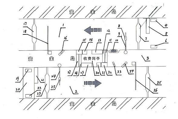
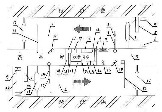
[0025]A multi-functional toll lane control and management system for toll roads. An entrance lane wheel axle identifier 5, an entrance lane ground sense coil 7 and an entrance lane drop rod coil 17 are installed on the ground of an entrance lane 1. The two sides of entrance driveway infrared transmitter 6 and entrance driveway infrared receiver 4 are installed respectively, on the ground of exit driveway 2, exit driveway axle discriminator 21, exit driveway sense coil 23, exit driveway weighing ground scale 20 and Exit lane drop bar coil 35, exit lane infrared transmitter 19 and exit lane infrared receiver 22 are respectively installed on the both sides of the entrance of exit lane 2, on the toll booth safety island 3 in the middle of entrance lane 1 and exit lane 2 The left end is respectively equipped with the entrance ...


PUM


Abstract

The invention discloses a multi-functional toll collection lane controlling and managing system of toll roads. An industrial personal computer, a car controlled machine, an IC (integrated circuit) card reader, a toll special keyboard and a display screen at an entrance lane direction are arranged in a toll booth; an entrance lane IC card automatic card sender and an entrance lane full-automatic toll data wireless emitter/receiver are arranged at the right side of the toll booth; the industrial personal computer, the car controlled machine, the IC card reader, the toll special keyboard and the display screen at an exit lane direction are arranged in the toll booth; and an exit lane full-automatic toll data wireless emitter/receiver is arranged at the left side of the toll booth. The system of the invention can organically combine three functions of manual toll lane, ETC (electronic toll collection) lane and automatic card sending and reading lane, so that various of vehicles can pass through the entrance and exit lanes of the toll station in a short time; and the system can disperse the vehicles on the square to a maximum extent without building new lanes. The system is safe and quick. In addition, the system can accelerate vehicle traffic capacity and reduce labor intensity of the toll staff.

Description

technical field [0001] The invention relates to a highway toll collection system, in particular to a multifunctional toll lane control and management system for toll highways. Background technique [0002] With the continuous development and construction of expressways and national first-class highways, the ways and means of toll collection are also constantly developing and changing. Weighing billing, charging methods are becoming more and more advanced. With the progress and development of society, the implementation of automatic toll collection on expressways and national first-class highways will be the development trend of the toll road industry in my country, but it will take a long process to develop. The non-stop toll lanes (intelligent traffic controller ETC) installed in some toll stations in Jiangxi Province is a fully automatic toll lane. At present, it is only for VIP customers such as free cars and cars. It is understood that at present, the use of fully autom...

Claims


Application Information

Patent Timeline
Patent Type & Authority Applications(China)
IPC IPC(8): G07B15/06
Inventor 王铁中刘木根李斌胡泰结
Owner 王铁中
Why Eureka
Try Eureka