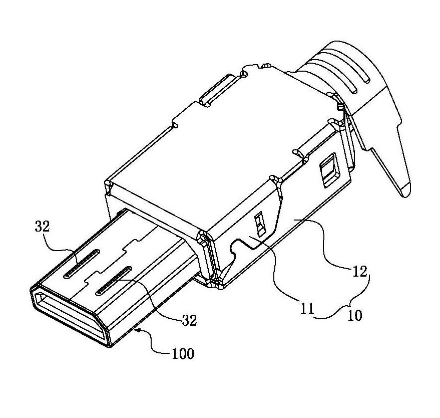
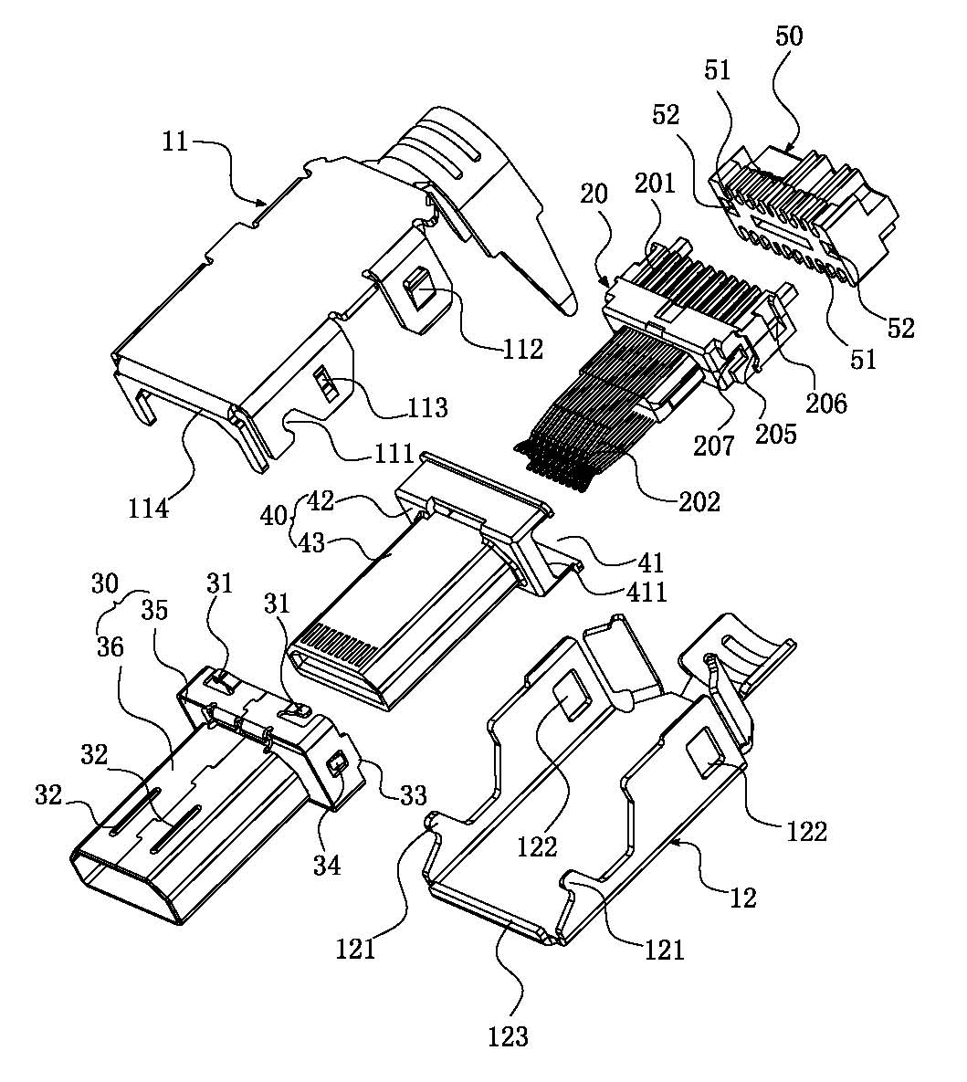
[0057] See Figure 1 to Figure 4 As shown, it shows the specific structure of the preferred embodiment of the present invention, including a shielding shell 10, a terminal module 20, a metal connecting shell 30, and an insulating sleeve 40. The insulating sleeve 40 is embedded in the metal connecting shell 30. A front-end plug interface is formed inside, and one end of the terminal module 20 is embedded in the insulating housing 40; the aforementioned shielding shell 10 is wrapped around the terminal module 20 and the metal connecting shell 30, and the metal connecting shell 30 is connected to the shielding shell 10 and The front end portion thereof is exposed outside the shielding shell 10 to form a plug-in part 100.
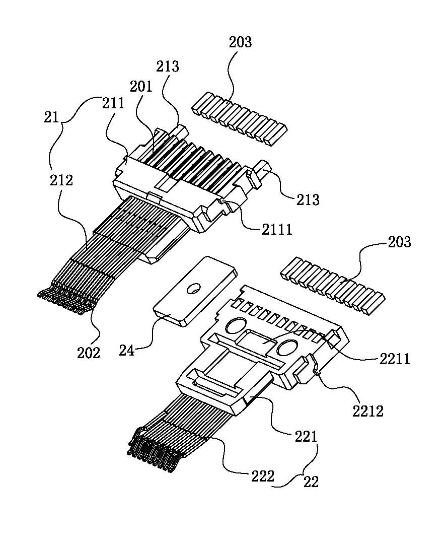
[0058] Wherein, the terminal module 20 includes a first terminal module 21 and a second terminal module 22 stacked one above the other. The first terminal module 21 includes a first terminal port 211 and is fixed on the first terminal port. The first terminal set 212 in the 211, the second terminal module 22 includes a second terminal port 221 and a second terminal set 222 fixed in the second terminal port 221, (Note: the first terminal port 211 Both the second terminal port and the second terminal port 221 include a wider base and a tongue extending forward from the front end of the base. After the first terminal module and the second terminal module are stacked together, the two bases and the two tongues Corresponding to each other.) The first terminal port 211 and the second terminal port 221 are attached to each other, and the first terminal group 212 and the second terminal group 222 are arranged at intervals. An embedding groove 2211 is opened on the bonding surface, and a reinforcing piece 24 is provided in the embedding groove 2211 to enhance the overall structural strength of the terminal module 20. When assembling, the reinforcing piece 24 is first placed in the aforementioned embedding groove 2211. Then, the aforementioned first terminal module 21 is correspondingly stacked on the second terminal module 22 to form the aforementioned terminal module 20; and, each terminal in the first terminal group 212 and the second terminal group 222 includes a contact Part 202 and welding part 201, the contact part 202 of which extends into the aforementioned insulating casing 40, and the welding part 201 is exposed at intervals at the rear end of the aforementioned first terminal port 211 and second terminal port 221, for each welding part 201 , The solder 203 is pre-added on the soldering part 201.
[0059] The metal connecting shell 30 is a cavity structure formed by stamping, bending, and joining thin metal plates. The cavity structure includes a wider shoulder 35 at the rear end and a smaller plug-in portion 36 at the front end; the metal The connecting shell 30 has front and rear openings, the front opening is a plug-in interface, and the top wall of the metal connecting shell 30 is provided with two elastic pieces 31 protruding outwardly near the rear opening. When the metal connecting shell 30 and the aforementioned shielding shell 10 when connected, the two elastic pieces 31 upwardly abut against the inside of the shielding shell 10, so that the shielding shell 10 and the metal connecting shell 30 are in stable contact to ensure the grounding effect; in addition, the top wall of the metal connecting shell 30 is provided near the front opening The arrangement of the two protruding portions 32 is beneficial to increase the strength of the plug-in connection between the electrical connector and the mating plug.
[0060] The shielding shell 10 includes a matching upper shell 11 and a lower shell 12, the side wall of the lower shell 12 is provided with a hook 121 near the front end, and the hook 121 is located on the plane of the side wall. Accordingly, the upper shell 11 is provided with a hook groove 111 on the side wall. Specifically, the hook portion 121 is formed obliquely upward from the side wall of the shielding shell 10, and has a convex portion protruding forward at the extension end. Accordingly, the hook groove 111 includes a chute opened on the side wall and a groove recessed forward on the front end of the chute, the chute communicates with the concave groove; and the side wall of the upper shell 11 is provided with an outward facing The protruding elastic clasp 112 is correspondingly provided with a notch 122 at the side wall of the lower shell 12 near the rear end. When the upper shell 11 and the lower shell 12 are assembled, the hook 121 can be hooked to the hook groove first. In 111, the rear end of the upper shell 11 is inserted downward into the rear end of the lower shell 12, so that the aforementioned elastic buckle 112 is locked into the notch 122, so that the upper and lower sides of the upper shell 11 and the lower shell 12 The front and rear directions are well positioned and connected.
[0061] In addition, combine Figure 2 to Figure 4 It can be seen that a first stop 2111 protrudes outwards on both sides of the first terminal port 211 near the upper end surface, and a second stop 2211 protrudes outwards on both sides of the second terminal port 221 near the upper end surface. When the first terminal module 21 and the second terminal module 22 are assembled together to form the terminal module 20, a groove 205 is formed between the first stop 2111 and the second stop 2211; and, the aforementioned The shape of the insulating casing 40 matches the aforementioned metal connecting casing 30, and it includes a wider shoulder 42 at the rear end and a smaller plug-in portion 43 at the front end. In this way, the insulating casing 40 can be very firmly embedded in the aforementioned In the metal connecting shell 30, the inserting portion 43 is embedded in the inserting portion 36 of the aforementioned metal connecting shell 30, and the shoulder 42 is limited to the shoulder 35 of the metal connecting shell 30. Of course, in order to further insulate the The sleeve 40 and the aforementioned metal connecting shell 30 can be better installed and positioned. The insulating sleeve 40 is provided with a slot 41 on both sides of the rear end. Accordingly, the rear ends of the aforementioned metal connecting shell 30 respectively protrude backward to form a limited Position 33; when the terminal module 20 is installed in the insulating housing 40, the first stop 2111 and the second stop 2211 are embedded in the grooves 41 on both sides of the insulating housing 40, and respectively abut against The top and bottom surfaces of the card slot 41, and then the insulating sleeve 40 and the terminal module 20 are inserted into the metal connecting shell 30 from the rear end opening of the metal connecting shell 30. The limit portion 33 of the metal connecting shell 30 It is clamped in the groove 205 between the first blocking portion 2111 and the second blocking portion 2211, so that the terminal module 20, the insulating sleeve 40 and the metal connecting shell 30 are firmly assembled together.
[0062] And, in the assembly and positioning between the various accessories, this embodiment is applied to figure 2 The elastic pieces 34 protruding inward on both side walls of the metal connecting shell 30 shown are matched with the groove 207 on the outer side of the terminal module 20. The elastic piece 34 is received in the groove 207, and the extended front end of the elastic piece 34 is clamped in On the front end surface 411 of the clamping groove 41 on both sides of the aforementioned insulating sleeve 40, it acts as an undercut, which facilitates the stable connection and positioning between the metal connecting shell 30 and the terminal module 20 and the insulating sleeve 40; in addition, the shielding shell The positioning protrusion 113 on the inner side wall of 10 is matched with the positioning groove 206 on the outer side of the terminal module 20, and the shielding shell 10 is provided with a baffle 114 at the front end of the upper shell 11 and a baffle 123 at the front end of the lower shell 12. Both the baffle 114 and the baffle 123 can resist the front end surface of the shoulder 35 of the metal connecting shell 30, which is beneficial to the positioning of the shielding shell 10 in the front and rear direction of the metal connecting shell 30. Both have simple structure and extremely high assembly positioning. Convenient features.
[0063] In order to facilitate the positioning of the connecting wire of the aforementioned electrical connector, a fixing seat 50 is further provided. The fixing seat 50 is provided with a wire positioning groove 51 corresponding to each of the aforementioned welding parts 201. When the corresponding wire and the aforementioned welding part 201 of the terminal module are completed After the welding operation, the wire can be positioned in the corresponding wire positioning groove 51 on the aforementioned fixing base 50, and then the aforementioned electrical connector can be assembled to the fixing base 50 for welding; image 3 It can be seen that the fixing base 51 is provided with a mounting hole 232, and the first terminal module 21 can be inserted into the mounting hole 232 of the fixing base 23 by pins for connection and positioning.
[0064] An assembling method of an electrical connector, including the steps
[0065] (1) Assemble the terminal module 20: prepare a first terminal module 21, a second terminal module 22, a reinforcement sheet 24 and a fixing seat 23, and place the reinforcement sheet 24 on the embedding of the second terminal module 21 In the groove 2211, the first terminal module 21 and the second terminal module 22 are then superimposed and assembled together, and then assembled on the fixing base 23 together to form the aforementioned terminal module 20;
[0066] (2) Assembling the terminal module 20 and the insulating housing 40: The assembled terminal module 20 is inserted into the insulating housing 40 from the rear end of the insulating housing 40 forward, and the base of the terminal module 20 is against Inside the shoulder 42 of the insulating sleeve 40;
[0067] (3) Assembling the metal connecting shell 30: The terminal module 20 and the insulating sleeve 40 assembled together are inserted into the metal connecting shell 30 forward from the rear end of the metal connecting shell 30, and the shoulder of the insulating sleeve 40 42 is pressed against the inner side of the shoulder 35 of the metal connecting shell 30;
[0068] (4) Assemble the shielding shell 10: first wrap the upper shell 11 above the terminal module 20, and then wrap the lower shell 12 below the terminal module 20 and buckle with the upper shell 11. The hook 121 of 12 is hooked in the hook groove 111 of the upper shell 11, and the elastic clasp 112 of the upper shell 11 is buckled in the groove 122 of the lower shell 12, then the aforementioned shielding shell 10 is covered outside the terminal module 20 , And the inside of the front end of the shielding shell 10 is sleeved on the outside of the rear end of the metal connecting shell 30;
[0069] In order to facilitate the positioning of the connecting wire of the aforementioned electrical connector, before the aforementioned step (4), and after the corresponding wire and the welding part 201 of the aforementioned terminal module have completed the welding operation, the wire can be positioned to the corresponding corresponding on the aforementioned fixing seat 50 In the wire positioning groove 51, the aforementioned electrical connector is assembled to the fixing base 50 for welding and fixing, and then the aforementioned process of assembling the shielding shell 10 is performed.
[0070] The key point of the design of the present invention is that according to the structure of the terminal module, an insulating casing and a metal connecting shell with matching shapes are provided. When assembling, the terminal module is put into the insulating casing, and then the insulating casing is embedded in the metal connecting shell. The shielding shell covers the terminal module and the metal connecting shell, which has a good shielding effect on the terminal module. At the same time, it effectively realizes the ground connection with the metal connecting shell. The front end of the metal connecting shell is exposed. The plug-in part is formed outside the shielding shell; the structure of the present invention is extremely compact, and the assembly is also very convenient, which is very suitable for making miniature electrical connectors; secondly, the first terminal module and the second terminal module are clamped It is equipped with a reinforcing sheet. When assembling, the reinforcing sheet is first placed in the recess of the second terminal module, and then the first terminal module and the second terminal module can be stacked, which greatly enhances the terminal module The overall structural strength improves the product quality and service life of the electrical connector, and the structural design of the first terminal module and the second terminal module in the present invention simplifies the mold forming process and manufacturing cost, and the aforementioned enhancement The assembly of the film is extremely convenient and fast.
[0071] The above are only the preferred embodiments of the present invention and do not limit the technical scope of the present invention. Therefore, any minor modifications, equivalent changes and modifications made to the above embodiments based on the technical essence of the present invention are still valid. It belongs to the scope of the technical solution of the present invention.