Ventilation of a high-pressure turbine in a turbomachine

A technology of high-pressure turbines and turbines, which is applied in the cooling of turbines/propulsion devices, cooling of engines, mechanical equipment, etc. It can solve problems such as unbalanced pressure and difficult control of turbines, and achieve the goal of reducing weight, reducing risks, and increasing service life Effect

Inactive Publication Date: 2011-09-14
SN DETUDE & DE CONSTR DE MOTEURS DAVIATION S N E C M A
View PDF10 Cites 6 Cited by
  • Summary
  • Abstract
  • Description
  • Claims
  • Application Information

AI Technical Summary

Problems solved by technology

[0017] This creates an unbalanced pressure on the rotor disk and, as a result, creates a downstream axial thrust on the rotor disk, making the turbine more difficult to control

Method used


Image

  • Ventilation of a high-pressure turbine in a turbomachine
  • Ventilation of a high-pressure turbine in a turbomachine
  • Ventilation of a high-pressure turbine in a turbomachine

Examples


Embodiment Construction

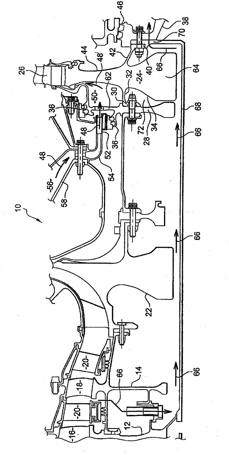
[0042] figure 1 A twin-rotor aircraft turbojet engine 10 of known type is shown, notably comprising (from upstream to downstream) a high-pressure compressor, a combustion chamber and a high-pressure turbine.

[0043] The high pressure compressor comprises a rotor consisting of disks 12, 14 with blades 16, 18 between which a stator stage 20 is placed for directing the flow of air through the compressor. The high-pressure compressor is provided with a centrifugal impeller 22 at its outlet for delivering compressed air to the combustion chamber.

[0044] The high-pressure turbine basically comprises a rotor disk 24 with blades 26 extending within the flow section of the combustion gases exiting the combustion chamber for the purpose of extracting mechanical energy from the gas flow in order to transmit rotational power to the high-pressure turbine and Rotor of high pressure compressor. Around the blades 26 of the rotor disk are sector-shaped sealing rings (not shown) which are ...


PUM


Abstract

Turbomachine high-pressure turbine comprising a rotor disc (24) with upstream (30, 32) and downstream (40, 42) annular flanges separating a radially internal annular cavity (72) in which the hub (64) of the disc (24) extends from two radially external annular cavities of which one (50) is upstream of the disc and receives a ventilation air flow (48) and of which the other (88) is downstream of the disc, the upstream flange (30, 32) of the disc comprising means (74) connecting the upstream external cavity (50) and the internal cavity (72) for ventilating the hub (64) of the disc (24).

Description

technical field [0001] The present invention relates to the ventilation of high-pressure turbines of twin-rotor turbines, such as aircraft turbojets, and in particular to the ventilation of high-pressure turbine disks. Background technique [0002] A twin rotor turbine has a high pressure turbine located at the exit of the combustion chamber for the purpose of extracting energy from the flow of gases emerging from the combustion chamber and transferring the rotational power to a high pressure compressor upstream of the combustion chamber in order to deliver pressure to said combustion chamber Air. This turbine also includes a low-pressure turbine downstream of the high-pressure turbine to extract additional energy from the gas flow and to transfer rotational power to a low-pressure compressor upstream of the high-pressure compressor. [0003] A high-pressure turbine generally includes a turbine disk at the outlet of the combustion chamber with blades rotated by the gas flow...

Claims


Application Information

Patent Timeline
Patent Type & Authority Applications(China)
IPC IPC(8): F01D5/08F02C7/18
CPCF01D5/082Y02T50/671F01D5/087F05B2260/205F02C7/18Y02T50/676F05D2260/205Y02T50/60
Inventor 马蒂厄·达科斯基法布里斯·加林戴尔芬·卢森-勒鲁威尔弗里德·施威布林
Owner SN DETUDE & DE CONSTR DE MOTEURS DAVIATION S N E C M A
Why Eureka
Try Eureka