Condensate removal by means of condensate evaporation in a refrigeration device

A technology for cooling equipment and condensed water, which is applied in lighting and heating equipment, household refrigeration equipment, defrosting, etc., can solve technical troublesome and expensive problems, and achieve the effects of reducing operating costs, compact structure, and reducing costs

Inactive Publication Date: 2011-09-14
威图有限公司
View PDF6 Cites 2 Cited by
  • Summary
  • Abstract
  • Description
  • Claims
  • Application Information

AI Technical Summary

Problems solved by technology

This solution is technically very complex and therefore expensive to implement, and additional energy is required for electrical heating of the condensate evaporator

Method used


Image

  • Condensate removal by means of condensate evaporation in a refrigeration device
  • Condensate removal by means of condensate evaporation in a refrigeration device
  • Condensate removal by means of condensate evaporation in a refrigeration device

Examples


Embodiment Construction

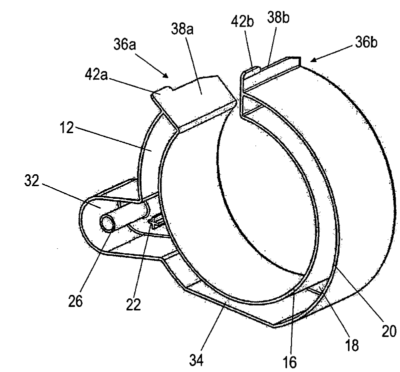
[0028] figure 1 The condensate evaporator is shown as a one-piece plastic die-cast part. The condensate evaporator has a receiving chamber 12 which is designed as a substantially C-shaped collecting trough 12 . The accommodating chamber 12 has a substantially right-angled cross-section that is open upwards and has a thin inner wall 16 , a bottom 18 and an outer wall 20 . This receiving chamber 12 can be connected to a feed hose (not shown) which conducts condensate accumulated on the (not shown) evaporator into the receiving chamber 12 . For this purpose, a stop element 22 is integrally formed on the bottom 18 of the collecting chamber 12 . The retaining element 12 is designed as a cross-shaped sleeve, so that when the supply hose is plugged in, condensation water can flow into the receiving chamber 12 between the cross-shaped ribs of the cross-shaped sleeve.

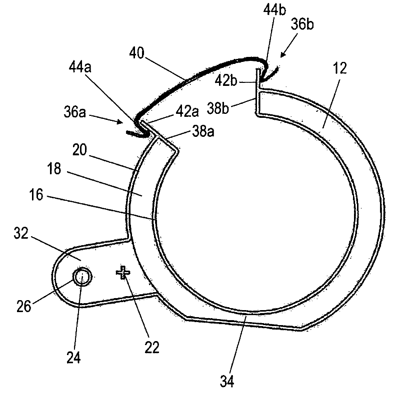
[0029] figure 2 In a schematic top view showing the figure 1 condensate evaporator. The bottom 18 of the recei...


PUM


Abstract

The invention relates to a condensate evaporator for a refrigeration device, comprising at least one evaporator and a compressor (10). The condensate evaporator comprises a receiving chamber (12) for the condensation water to be evaporated and developing in the refrigeration device. The receiving chamber (12) is in thermal contact with the compressor (10) and is heated by the exhaust heat of the compressor (10) in order to produce water vapor from the condensation water.

Description

technical field [0001] The invention relates to a cooling device, in particular for switchboards, having a refrigeration circuit with an evaporator, a liquefier and a compressor, wherein accumulated condensate is evaporated in a condensate evaporator with a condensate receiving chamber. Background technique [0002] Such cooling devices are used, for example, to condition the air in switchboards, in which a series of electronic components are housed, which emit enormous power losses (in the form of heat). Condensate that accumulates on the evaporator drips off and collects in the condensate collection container located below it. It is known that the condensate is transported by means of a suction device from the condensate collection container to an electrically heated condensate evaporator, where the condensate is vaporized and discharged into the surroundings as water vapor. [0003] Whether the filling limit of the condensate in the condensate collection container has be...

Claims


Application Information

Patent Timeline
IPC IPC(8): F25D21/14
CPCF25D2321/143F25D2321/146F25D21/14
Inventor 曼弗雷德·伊梅尔
Owner 威图有限公司
Why Eureka
Try Eureka