High-frequency radiation heating device

A high-frequency heating device and high-frequency technology, applied in electric heating devices, microwave heating, electric/magnetic/electromagnetic heating, etc., can solve the problems of high-frequency heating, which takes a lot of time, cannot be detected separately, and the high-frequency generating unit is unclear. , to achieve the effect of high-efficiency heating conditions

Active Publication Date: 2013-05-01
PANASONIC CORP
View PDF1 Cites 0 Cited by
  • Summary
  • Abstract
  • Description
  • Claims
  • Application Information

AI Technical Summary

Problems solved by technology

[0008] However, in the structure of the conventional high-frequency heating device disclosed in Patent Document 1, in the so-called backflow wave input from the heating chamber to a certain radiation part, it is impossible to detect the radiation from one radiation part of the high-frequency generating unit. The radiated high frequency is reflected and returns to the radiation part of the reflected wave, and the high frequency emitted by the radiation part of the other high frequency generating unit is input into the radiation part of one high frequency generating unit.
Therefore, among the high frequencies radiated by a certain radiation unit itself, the total of the reflected wave reflected back to the radiation unit and the passing wave input to other radiation units is calculated, and the individual high-frequency generating units are not known. The problem of high frequency radiation loss
That is, it is not known which high-frequency generating unit has a higher ratio of radiation loss in the radiation loss of the entire high-frequency heating device. Therefore, when suppressing radiation loss, it is not clear which high-frequency generating unit should be controlled. The optimization handles the problem that takes a lot of time

Method used


Image

  • High-frequency radiation heating device
  • High-frequency radiation heating device
  • High-frequency radiation heating device

Examples


Embodiment Construction

[0023] Hereinafter, the high-frequency heating device 100 according to the embodiment of the present invention will be described with reference to the drawings.

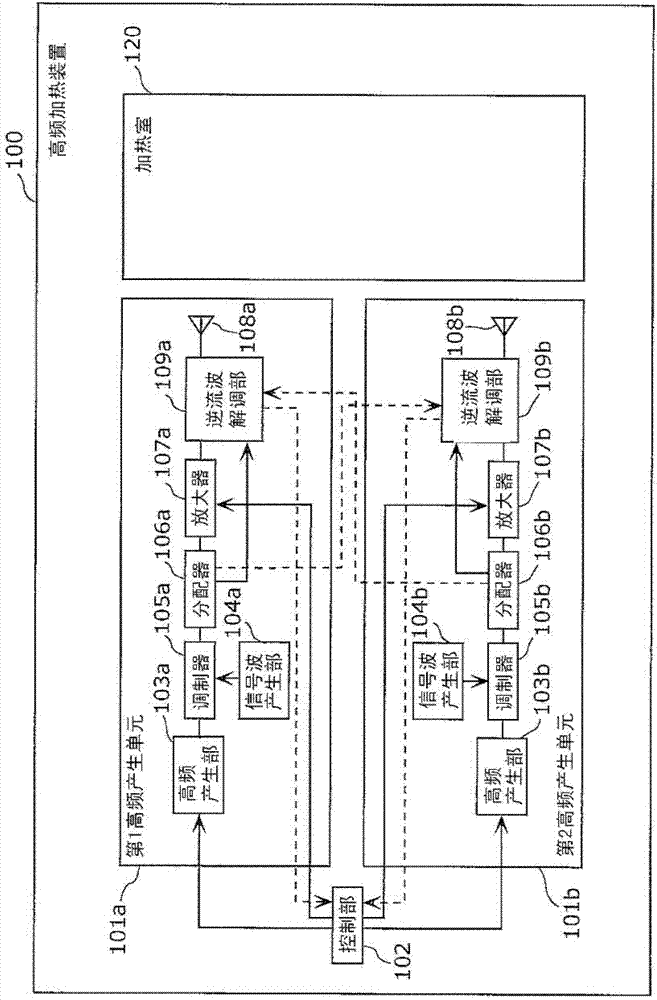
[0024] figure 1 It is a block diagram which shows the structure of the high frequency heating apparatus 100 concerning embodiment of this invention.

[0025] like figure 1 As shown, the high frequency heating apparatus 100 concerning embodiment of this invention is provided with the 1st high frequency generation unit 101a and the 2nd high frequency generation unit 101b, the control part 102, and the heating chamber 120 which accommodates the to-be-heated object.

[0026] First, the first high-frequency generating unit 101a and the second high-frequency generating unit 101b will be described.

[0027] The first high-frequency generating unit 101a is a high-frequency generating unit that radiates a predetermined high frequency to the heating chamber 120, and includes a high-frequency generating unit 103a, a signal wa...


PUM


Abstract

A radio-frequency heating apparatus includes a heating chamber, first and second radio-frequency wave generation devices from which radio-frequency waves are radiated, and a control unit that controls the first and second radio-frequency wave generation devices. Each of the first and second radio-frequency wave generation devices includes: a radiation unit that radiates radio-frequency waves into the heating chamber; and a backward wave demodulation unit that demodulates backward waves entering from the heating chamber. The backward wave demodulation unit of the first radio-frequency wave generation device detects reflected waves that are radio-frequency waves radiated from the radiation unit and reflected back into the radiation unit, and through waves that are radio-frequency waves radiated from another radiation unit and enter the radiation unit. The control unit controls the first and second radio-frequency wave generation devices based on the detected reflected waves and through waves.

Description

technical field [0001] The present invention relates to a high-frequency heating device, and more particularly, to a high-frequency heating device including a plurality of high-frequency generating units using semiconductor element amplifiers. Background technique [0002] Conventional high-frequency heating apparatuses are generally constituted by oscillating equipment using a vacuum tube called a magnetron. [0003] In recent years, a high-frequency heating apparatus using an oscillator and an amplifier using a semiconductor element instead of the magnetron has been studied. In the case of such a high-frequency heating device, the frequency can be easily controlled with a small and inexpensive structure. In Patent Document 1, it is disclosed to detect the reverse current wave under various conditions when the phase difference and frequency of the high frequency radiated from the respective radiation parts of the plurality of high frequency generating units are changed, an...

Claims


Application Information

Patent Timeline
Patent Type & Authority Patents(China)
IPC IPC(8): H05B6/74H05B6/64H05B6/66H05B6/68
CPCH05B6/705
Inventor 石崎俊雄
Owner PANASONIC CORP
Why Eureka
Try Eureka