A self-balancing plunger-type upper spraying laminar flow cooling device

A cooling device and balancing device technology, applied in metal processing equipment, metal rolling, manufacturing tools, etc., can solve the problems of high failure rate, high production and maintenance cost, consumption, etc., to reduce temperature drop, improve work stability, Ensure the effect of plate shape

Active Publication Date: 2011-09-21
BAOSHAN IRON & STEEL CO LTD
View PDF5 Cites 3 Cited by
  • Summary
  • Abstract
  • Description
  • Claims
  • Application Information

AI Technical Summary

Problems solved by technology

However, after a period of actual production, the inventor found that the device had a high failure rate during production and use, which required excessive production and maintenance costs.

Method used


Image

  • A self-balancing plunger-type upper spraying laminar flow cooling device
  • A self-balancing plunger-type upper spraying laminar flow cooling device
  • A self-balancing plunger-type upper spraying laminar flow cooling device

Examples


Embodiment Construction

[0040] Attached below Figure 1-8 A preferred embodiment of the present invention is specifically introduced.

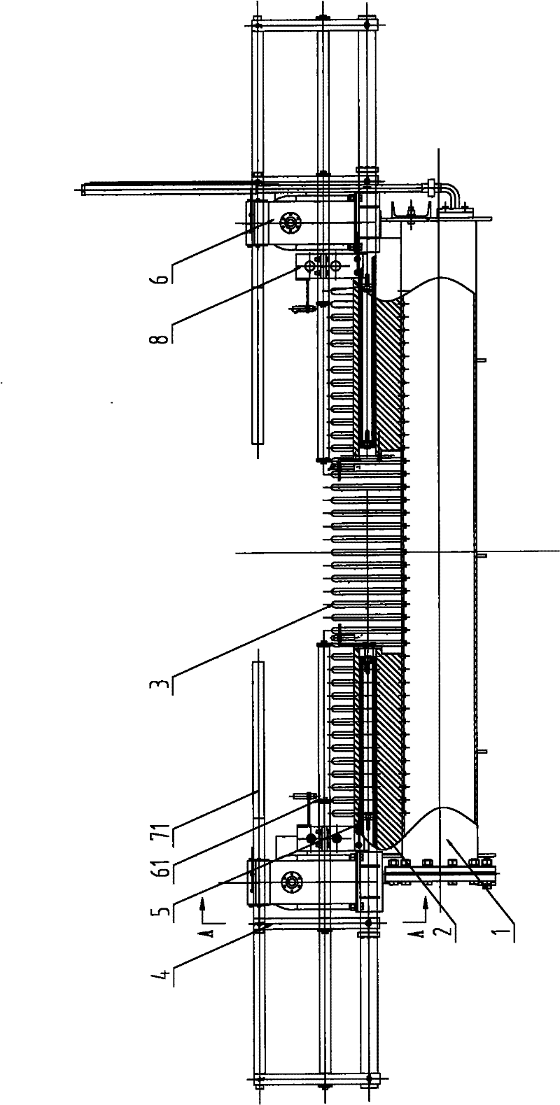
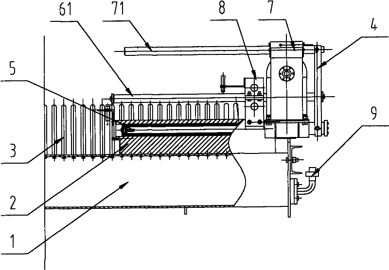
[0041] Such as figure 1 and figure 2As shown, the self-balancing plunger type upward spraying laminar flow cooling device in this embodiment includes several groups of upward spraying devices, and each group of upward spraying devices includes: a header 1 fixedly arranged along the running direction of the vertical strip steel; A number of gooseneck nozzles 3 are evenly distributed on the tube 1, and the beam 2 is divided into two sections and arranged above the two ends of the header 1, and the beam 2 is provided with a number of through holes along the vertical direction for conducting the header 1 and each nozzle 3 , the beam 2 is provided with a plunger hole along the horizontal direction, the plunger hole is connected with the through hole, the diameter of the plunger hole is greater than or equal to the diameter of the through hole, the plunger 5 is arranged...


PUM


Abstract

The invention discloses a self-balancing plunger-type upper spraying laminar flow cooling device which comprises a plurality of groups of upper spraying devices. Each group of upper spraying device comprises a collecting pipe, a plurality of spraying pipes, a cross beam, two plungers , two sets of driving devices and two sets of balancing devices, wherein the cross beam is arranged at both ends of the collecting pipe; a plunger hole is arranged in the cross beam along the horizontal direction; the two plungers are respectively arranged at both ends of the plunger hole; the two sets of drivingdevices are respectively arranged at both ends of the collecting pipe and connected with the two plungers; and the two sets of balancing devices are respectively arranged above the two sets of driving devices, each set of balancing device is correspondingly and fixedly connected with each set of driving device and the plunger through a synchronization board. Compared with the prior art, the self-balancing plunger-type upper spraying laminar flow cooling device can automatically guarantee the force balance of the driving devices when regulating the laminar flow cooling width, thereby improvingthe work stability, and avoiding the deflection torque which is caused by the single-side force of the driving devices and can affect the stability of plunger drive.

Description

technical field [0001] The invention relates to a laminar flow cooling device, in particular to an upper spray laminar flow cooling device with adjustable width on one side in the hot rolling cooling process. Background technique [0002] The laminar flow cooling device is used in the hot rolling and continuous rolling mill production lines of iron and steel enterprises. Its main function is to quickly cool the strip steel exported from finish rolling according to the target temperature set by coiling to ensure the product performance of the strip steel. [0003] Taking the hot rolling mill as an example, its laminar flow cooling device has a total of 76 sets of cooling headers (corresponding to one set of upper and lower). Among them, the first 68 groups are the main cooling section, and the last 8 groups are the refined cooling section. It is generally divided into several cooling zones, and each cooling zone has its own main cooling section and the cooling section of the...

Claims


Application Information

Patent Timeline
Patent Type & Authority Applications(China)
IPC IPC(8): B21B45/02
Inventor 王军
Owner BAOSHAN IRON & STEEL CO LTD
Why Eureka
Try Eureka