Robot system

A robot system and robot technology, applied in the field of robot systems, can solve problems such as increased equipment costs and robots exceeding the limit range

Active Publication Date: 2014-07-23
YASKAWA DENKI KK
View PDF6 Cites 0 Cited by
  • Summary
  • Abstract
  • Description
  • Claims
  • Application Information

AI Technical Summary

Problems solved by technology

[0004] In addition, the range limit of each axis of the existing robot is to limit the command value and the current motor position, and the robot will exceed the limit range due to emergency stop, etc.
Therefore, there is a problem that the equipment cost is increased by realizing range limitation by a mechanical device such as a mechanical limiter.

Method used


Image

  • Robot system
  • Robot system
  • Robot system

Examples


Embodiment 1

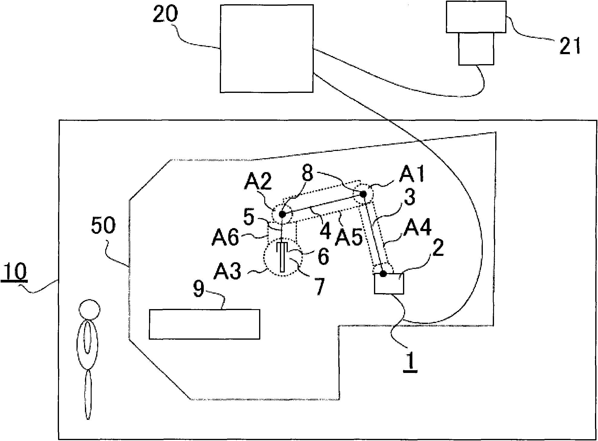
[0029] In this example, the robot 1 has a base 2 and three arms 3 , 4 , 5 . A tool 7 is provided on the arm 5 via a gripping device 6 . As the tool 7, a welding torch for arc welding, a torch for spot welding, a hand for carrying, and the like are attached. Joints 8 are used to connect arms 3, 4, and 5, respectively. The workpiece 9 is an object to be welded, a conveyed object, or the like. For example, in the safety fence 10, welding of the workpiece|work 9 and assembly work of a conveyance are performed.

[0030] A necessary signal is sent from the control device 20 to the robot 1, and the arms 3, 4, 5 perform predetermined movements according to a predetermined operation program, and the gripping device 6 or tool 7 moves along a desired trajectory.

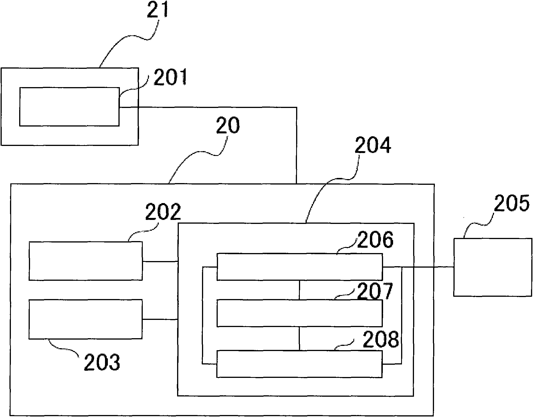
[0031] A teaching tool 21 is connected to the control device 20, and performs teaching to the robot 1, rewriting of work programs, and the like.

[0032] Before the robot is introduced, installed, and operated, the virtual ...

Embodiment 2

[0082] As the configuration of Example 2, using Figure 6 An embodiment in which the aforementioned monitoring and stop control devices are made independent will be described.

[0083] Figure 6 is true figure 2The configuration of the operating region monitoring device 601 is added to the system. The operating area monitoring device 601 obtains the current position of the robot (the position of the workpiece or tool) through the drive unit 205 in each specified monitoring period according to the position of the motor 605 of each axis. For the current position of the robot, it touches and monitors the position on the virtual safety barrier. Contact with the virtual safety barrier is checked in section 604 . In addition, based on the motor position 605 information read by the current position detection unit 602 , the coasting predicted position calculation unit 603 calculates the position where the motor coasts and stops when the emergency stop is performed at this point in...

Embodiment 3

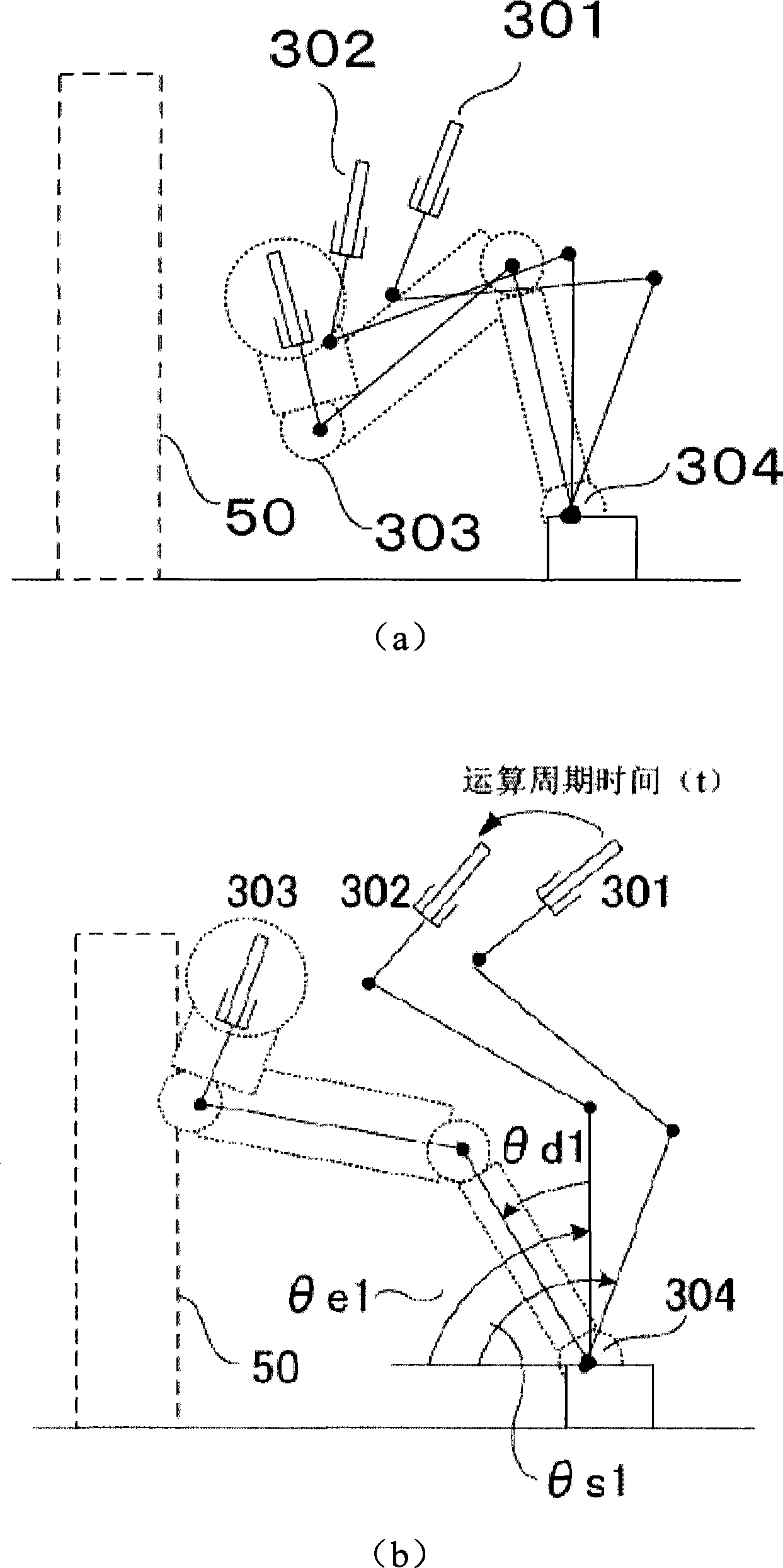
[0104] use Figure 8 A robot system including the robot motion limiting method and device of the third embodiment will be described. Mechanical safety devices such as mechanical limiters are installed on each axis of a general robot to limit the movement of each axis of the robot. On the other hand, instead of the mechanical limiter, it is possible to reduce the mechanical limiter by defining and monitoring the movable range 60 of each axis.

[0105] Figure 9 It is a diagram showing another structure of the third embodiment, and an embodiment in which the operation restriction of each axis is performed in the above-mentioned monitoring and stop control device will be described.

[0106] The next target position is calculated in the next target position calculation unit 206 . With respect to the next target position obtained here, it is checked in the movement range limit monitoring unit 901 of each axis whether the movement exceeds the movement range 60 of each axis. In a...


PUM


Abstract

The present invention can effectively utilize the ground space of factories and the like while improving the safety of robot operation, and can simplify equipment. It is processed in the following order and defined on the memory: the arm occupation area including the workpiece and tool of the arm and wrist of the robot; the virtual safety fence that the arm cannot touch; and the movable range of each axis, based on the inertia measured actually Estimate the inertial movement angle of each axis of the robot when the robot is suddenly stopped during the execution of the motion command to the next target position, and calculate the predicted inertial movement position of the robot by adding it to the next target position. Control to stop the robot immediately when abnormality is confirmed whether the arm occupied area at the movement prediction position is in contact with the virtual safety fence or whether the position of each axis of the robot is within the operable range.

Description

technical field [0001] The invention relates to a robot system that limits the range of motion of a robot. Background technique [0002] As an existing robot system, as shown in Japanese Patent Publication No. 2004-322244, the area used to limit the movement of the robot is defined as a "virtual safety barrier" on the memory, and at least two places including workpieces and tools are defined. In a part of the three-dimensional space area, the predicted position in the trajectory calculation of the three-dimensional space area is searched for the virtual safety barrier, and even if only a part of the three-dimensional space area touches the virtual safety barrier, the robot is controlled to stop. [0003] However, in the prior art, the robot is stopped when the predicted position on the trajectory calculation exceeds the virtual safety barrier, because even if the robot stops due to an emergency stop or the like when the predicted position on the trajectory calculation is not...

Claims


Application Information

Patent Timeline
Patent Type & Authority Patents(China)
IPC IPC(8): B25J9/16B25J19/06B25J19/04B25J13/00
CPCB25J9/1676G05B2219/39098
Inventor 前原伸一假屋崎洋和前田贵宏
Owner YASKAWA DENKI KK
Why Eureka
Try Eureka