Direct heat setting method and device for two-for-one twisting

A technology of heat setting and heat setting, which is applied in the direction of textiles and paper making, and can solve the problems of easy bruising of winding bobbins, uneven heat setting, long process route, etc., achieve good consistency, reduce back and forth handling, and short process flow Effect

Inactive Publication Date: 2011-09-21
绍兴华裕纺机有限公司
View PDF3 Cites 3 Cited by
  • Summary
  • Abstract
  • Description
  • Claims
  • Application Information

AI Technical Summary

Problems solved by technology

[0004] There are some defects in the process of adopting vacuum heat setting: 1. Uneven heat setting
2. The process route is long
Moreover, during the multiple handling of the winding bobbin, the winding bobbin is easy to be damaged
3. Energy waste
[0005] Since the above-mentioned process has been applied in this field, various manufacturers have been accustomed to using it. Therefore, for a long time, no one has proposed changes to it to correct the defects in the process.

Method used


Image

  • Direct heat setting method and device for two-for-one twisting
  • Direct heat setting method and device for two-for-one twisting
  • Direct heat setting method and device for two-for-one twisting

Examples


Embodiment 1

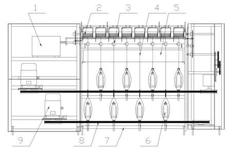
[0033] like image 3 A double-twisting direct heat-setting device is shown, the motor 9 is mounted on the frame 7, the dragon belt 8 is linked with the motor 9, the double-twisting spindle 6 is linked with the dragon belt 8, and a double-twisting spindle 6 is provided above. The biphenyl heating and setting box 5 is installed, and the winding mechanism 2 is installed above the biphenyl heating and setting box 5 , and the gear box 1 is linked with the winding mechanism 2 . An overfeeding roller 3 is provided between the biphenyl heating and setting box 5 and the double twisting spindle 6, and between the biphenyl heating and setting box 5 and the winding mechanism 2, respectively.

[0034] During operation, the motor 9 drives the belt 8 to move, and the belt 8 drives the double-twisting spindle 6 to rotate, completing the double-twisting and twisting of the twisted yarn 4. The twisted yarn 4 passes through the overfeeding roller 3, adjusts the tension and enters the heat settin...

Embodiment 2

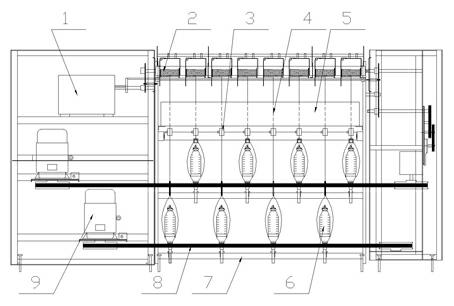
[0036] like figure 1 As shown, the basic structure is the same as that of Embodiment 1, the difference is that one overfeeding roller 3 is provided, that is, one overfeeding roller 3 is provided between the biphenyl heating and setting box 5 and the winding mechanism 2, and the setting in the biphenyl heating The overfeed roller between the setting box 5 and the double twisting spindle 6, in this way, the twisted yarn 4 directly enters the heat setting box 5 for heat setting after being twisted from the double twisting spindle 6. Other procedures are the same as in Example 1.

Embodiment 3

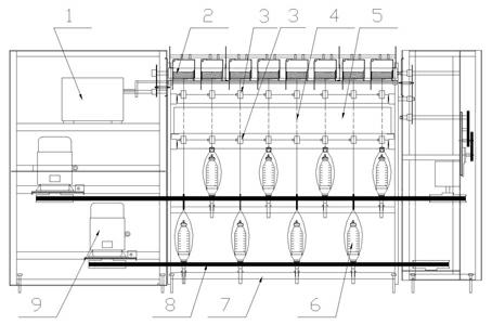
[0038] like figure 2 As shown, the basic structure is the same as that of Embodiment 1, the difference is that the overfeed roller 3 is set to one, that is, an overfeed roller is provided between the biphenyl heating and setting box 5 and the double twisting spindle 6, and the setting in the biphenyl heating setting box 6 is cancelled. The overfeeding roller 3 between the box 5 and the winding mechanism 2, after the twisted yarn is twisted by 4 times, after the tension is adjusted by the overfeeding roller 3, it enters the heat setting box 5 for heat setting, and the twisted yarn 4 is heated from the heat setting. After the box 5 comes out, it directly enters the winding mechanism and is wound into a forming bobbin.


PUM


Abstract

The invention discloses a direct heat setting method and device for two-for-one twisting, belonging to the technical fields of textiles. A heat setting box is additionally arranged above a two-for-one twisting spindle of a two-for-one twisting machine, twisted yarns are directly subjected to heat setting and then subjected to winding setting. Twisted monofilaments are subjected to heat setting by means of the direct heat setting process for two-for-one twisting at constant temperature and constant speed, so that the setting effect is improved. A technological process of subsequent vacuum heat setting for two-for-one twisting in the prior art is omitted, so that labor and electricity are saved.

Description

Technical field: [0001] The invention relates to a double twist direct heat setting method and a device thereof, belonging to the technical field of textile machinery. Background technique: [0002] For clothing woven with twisted silk, the raw material is twisted by a double twisting machine. After twisting, the conventional process is to undergo heat setting. [0003] At present, the double-twisting heat-setting process used for a long time in the field is that after the twisted yarn is double-twisted and twisted, it is wound into a forming bobbin, and then vacuum heat-setting is performed. The specific steps are as follows: the commonly used heat setting equipment is a vacuum heat setting box, the twisted winding bobbin is put into the vacuum heat setting box, and the twisted yarn is heated and shaped with steam. Since the twisted yarn on the winding drum has been wound with a thicker tube of yarn, in order to heat the twisted yarn through, it is necessary to vacuumize ...

Claims


Application Information

Patent Timeline
Patent Type & Authority Applications(China)
IPC IPC(8): D01H13/28D01H13/10
Inventor 刘光容朱爱萍
Owner 绍兴华裕纺机有限公司
Why Eureka
Try Eureka