Vortex type fluid machine and assembling method thereof
A kind of fluid machinery and scroll technology, applied in the field of scroll compressors, to achieve the effect of improving energy efficiency and high energy efficiency
- Summary
- Abstract
- Description
- Claims
- Application Information
AI Technical Summary
Problems solved by technology
Method used
Image

Examples
Embodiment 1
[0035] use Figure 1 ~ Figure 7 The embodiment 1 of the present invention is described.
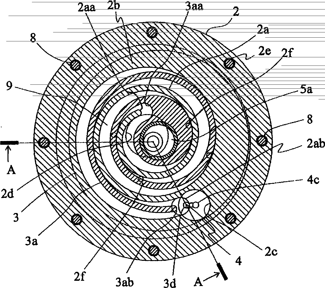
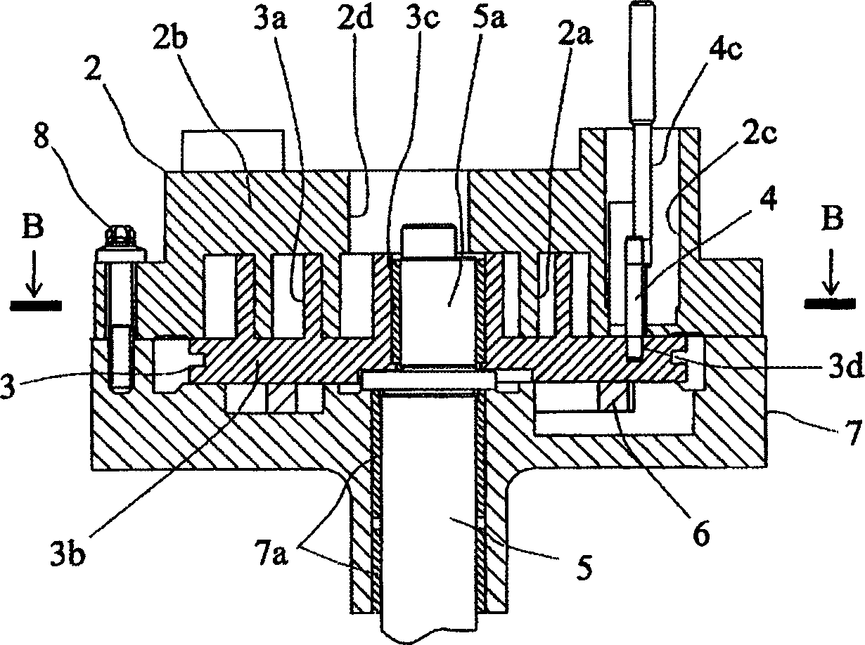
[0036] figure 1 It is a plan cross-sectional view showing the shaft through scroll compressor of the scroll-type fluid machine of this embodiment, and figure 2 The B-B section is equivalent. figure 2 Yes figure 1 The longitudinal section view is with figure 1 The A-A section is equivalent.
[0037] In these figures, the compression mechanism unit 1 is composed of a frame body 7, a fixed scroll 2 attached to the frame body 7, an orbiting scroll 3 meshed therewith, and the like. In a hermetic compressor, usually the frame 7 is fixed to a hermetic container (not shown), and the fixed scroll 2 is fixed by fixing bolts 8 passing through a plurality of cavities 2e provided in the outer periphery of the fixed scroll 2 On the frame 7.
[0038] The fixed scroll 2 is provided with a mirror plate 2b, a scroll-shaped coil 2a erected on the mirror plate 2b, a suction port 2c provided on the outer peripher...
Embodiment 2
[0053] Next, use Figure 8 ~ Figure 10 Example 2 of the present invention will be described. This embodiment shows an example of applying the present invention to a scroll-type fluid machine having a structure in which the crankshaft does not penetrate the orbiting scroll member. In these figures, the parts assigned the same reference numerals as in the above-mentioned Example 1 indicate the same or equivalent parts. In this embodiment, the orbiting scroll 3 is erected on one side of the mirror plate with a scroll-shaped winding plate, and a orbiting bearing 3c for driving the orbiting scroll is provided near the center of the opposite surface (back side). The crank part of the crankshaft is inserted in the orbiting bearing 3c.
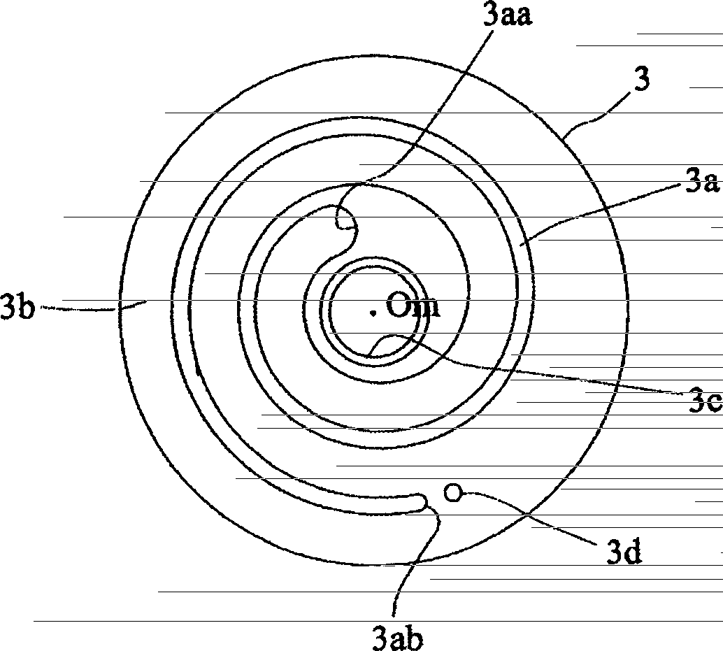
[0054] Figure 8 Is equivalent to Example 1 Figure 5 The figure with Figure 5 In the same way, the center Om of the orbiting scroll 3 is aligned with the center Of of the fixed scroll, and the orbiting scroll 3 is overlapped with a one-dot chain line...
Embodiment 3
[0058] Next, use Picture 11 and Picture 12 Example 3 of the present invention will be described. In these figures, the parts assigned the same reference numerals as in the above-mentioned Example 1 and Example 2 indicate the same or equivalent parts. Picture 11 It is a top sectional view of the scroll type fluid machine of this embodiment, Picture 12 Is equivalent to Picture 11 A longitudinal section view of the E-E section. In the above-mentioned embodiments 1 and 2, the inflow of the working fluid into the compression mechanism adopts the longitudinal suction structure that enters the suction port of the fixed scroll from the axial direction, but in this embodiment, the present invention is applied to the fixed scroll A scroll-type fluid machine of a horizontal suction structure in which the axis of the scroll 2 is perpendicular (radial) is provided with a suction port 2c.
[0059] Compared with the vertical suction structure, the horizontal suction structure has the advan...
PUM
 Abstract
Description
Claims
Application Information
 - R&D
- Intellectual Property
- Life Sciences
- Materials
- Tech Scout
- Unparalleled Data Quality
- Higher Quality Content
- 60% Fewer Hallucinations
Browse by: Latest US Patents, China's latest patents, Technical Efficacy Thesaurus, Application Domain, Technology Topic, Popular Technical Reports.
© 2025 PatSnap. All rights reserved.Legal|Privacy policy|Modern Slavery Act Transparency Statement|Sitemap|About US| Contact US: help@patsnap.com