Dual clutch transmission

A dual-clutch transmission, clutch technology, applied in the direction of vehicle gearboxes, gear transmissions, transmission components, etc., can solve the problem of increasing gear fatigue, and achieve the effect of reducing possibility, reducing wear, and optimizing load distribution

Inactive Publication Date: 2011-09-21
ROMAX TECH
View PDF11 Cites 8 Cited by
  • Summary
  • Abstract
  • Description
  • Claims
  • Application Information

AI Technical Summary

Problems solved by technology

[0006] These arrangements where the highly loaded gears (2nd, 1st and reverse) tend to be at the ends of the countershafts have the greatest magnitude of gear misalignment and the resulting high contact stress, which increases the potential for gear fatigue

Method used


Image

  • Dual clutch transmission
  • Dual clutch transmission
  • Dual clutch transmission

Examples


Embodiment Construction

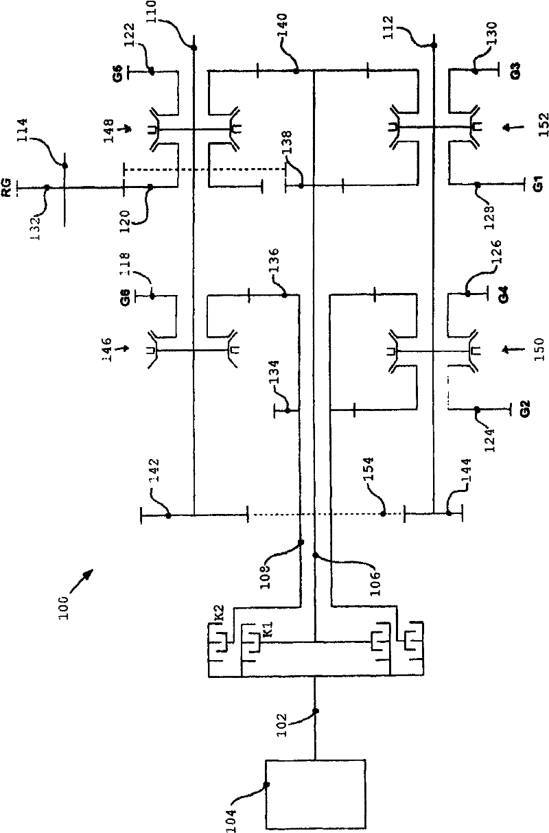
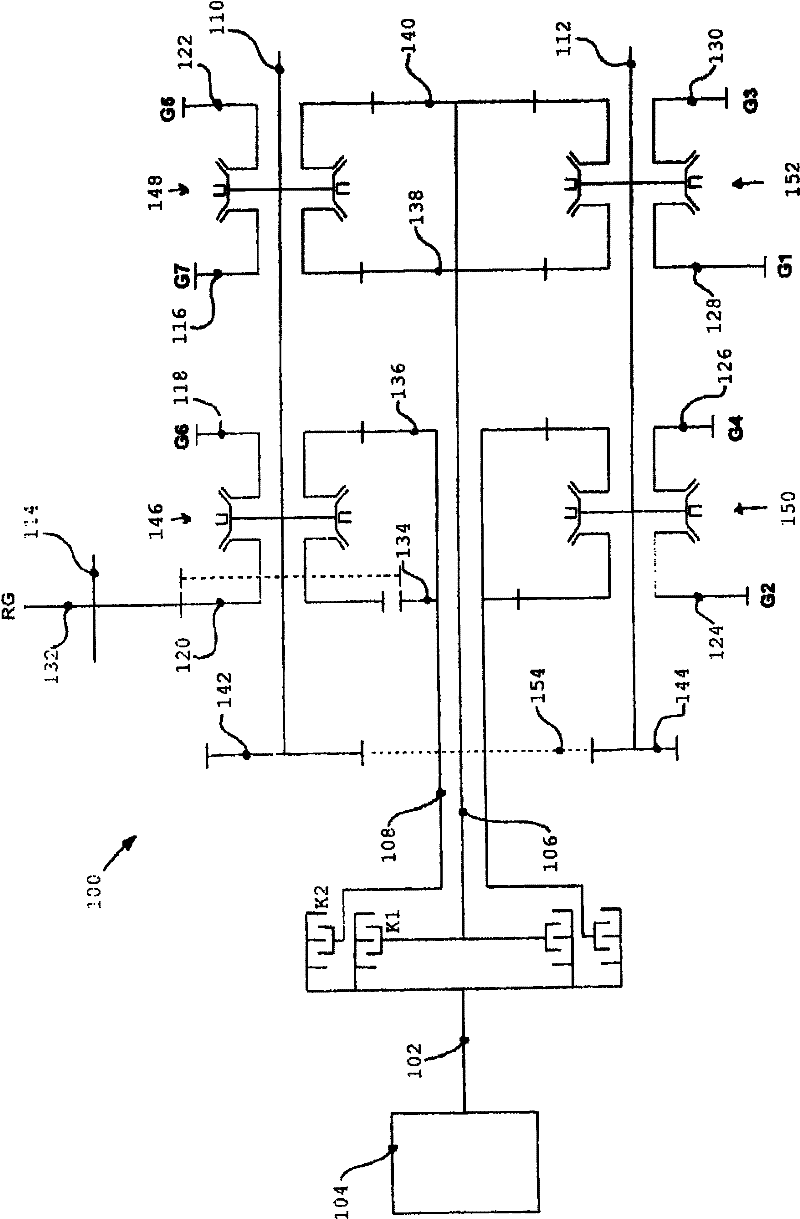
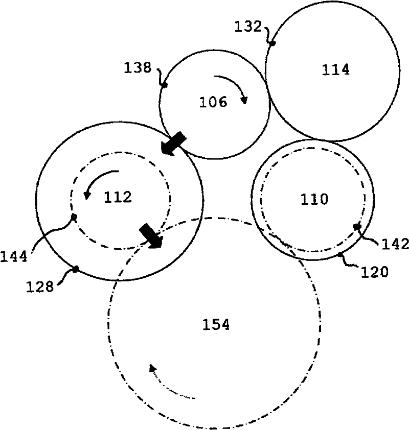
[0017] figure 1 3 shows a representative schematic diagram of the dual clutch transmission 100 of the present invention, with reference to figure 1 Turning to FIG. 3 , an embodiment of the present invention and its technical advantages can be better understood.

[0018] The first clutch K1 and the second clutch K2 are mechanically connected via a drive shaft 102 to a prime mover 104 in a conventional manner. Each clutch is also mechanically connected with the first input shaft 106 and the second input shaft 108 . The second input shaft is concentric with the first input shaft. Therefore, depending on the selected clutch, the driving force of the engine is applied to one of the input shafts. Fixed drive gears 134, 136 are connected to the first input shaft and fixed drive gears 138, 140 are connected to the second input shaft. The first output shaft 110 and the second output shaft 112 are arranged in parallel with respect to the input shaft. Driven idler gears 118, 120, 12...


PUM


Abstract

The invention relates to a dual clutch transmission. The dual clutch transmission has a reverse gear driven by a reverse driving gearwheel via an intermediate idler wheel freely rotatably mounted on an intermediate lay shaft, which avoids the need for a long intermediate lay shaft. The driving gearwheel, the intermediate idler wheel and the reverse driving gearwheel are aranged on the same plane. The transmission has a driving gearwheel and a driven gearwheel for first gear disposed on their respective input and output shafts at or near a centre of the transmission near a region on the output shaft where shaft bending is high. This is intended to minimise misalignment between gear meshes of the driving gearwheel and the driven gearwheel for first gear caused by flexure in the wheels, thereby reducing wear and noise as the gear meshes more efficiently enqage with each other. The low speed, high loaded gears (Gl/RG, G2; Gl, G2/RG) are disposed so that they alternate with the higher speed, lower loaded gears (G6/G4, G5/G3), thereby distributing load evenly along the shaft and reducing a likelihood of shaft fatigue.

Description

technical field [0001] The present invention relates to dual clutch transmissions. Background technique [0002] In a dual clutch transmission, each clutch is connected to an input shaft with a fixed drive wheel that engages a corresponding idler gear on a countershaft. The selector operates to secure one of the idler gears to the countershaft so that drive is transmitted by the clutch to the countershaft. [0003] This means that when one of the idler gears on one of the shaft pairs is selected in this way, the selector associated with the other shaft pair can sequentially select the next gear when the clutch corresponding to that pair is engaged , smooth gear changes can be accomplished. This means that one countershaft carries the odd gears, while the other will carry the even gears. [0004] The location of the reverse gear and how it operates has many different designs, generally the design includes an idler shaft connected by a second gear. This often results in an...

Claims


Application Information

Patent Timeline
Patent Type & Authority Applications(China)
IPC IPC(8): F16H3/091
CPCF16H3/006F16H2200/006
Inventor C·R·比安科Y·朴
Owner ROMAX TECH
Why Eureka
Try Eureka