
Cylindrical gasholder sealing device

A technology of a sealing device and a gas tank, applied in the sealing field, can solve the problems of increased wear of sealing rubber strips, sealing failure, insufficient sealing oil level of a piston oil groove, etc., and achieve the effect of improving safety.

Active Publication Date: 2011-09-21
CISDI ENG CO LTD
View PDF6 Cites 4 Cited by
  • Summary
  • Abstract
  • Description
  • Claims
  • Application Information

AI Technical Summary

Problems solved by technology

When the piston descends at a fast speed, due to the welding deformation and local deformation of the side plate of the cylinder, the sealing assembly may tip over to the piston box beam around the contact point between the bottom edge of the sealing rubber strip and the side plate. Once the sealing assembly Partial tilting towards the piston box beam, the horizontal force transmitted by the rubber pressing mechanism to the sealing rubber strip through the connecting rod will be greatly reduced, causing the sealing assembly to fail to reset. If the piston continues to descend, the adjacent rubber pressing mechanism will The sealing components in the position will be overturned in this way, forming a domino effect, resulting in seal failure; at the same time, when the piston descends rapidly, the oil attached to the side plate increases, resulting in insufficient oil level in the piston oil groove, which will also lead to seal failure. High piston oil level solves the problem, but the simple increase of the piston oil level leads to an increase in the differential pressure between the top and bottom of the sealing canvas, the pressure of the sealing rubber strip on the side plate of the cylinder increases, the wear of the sealing rubber strip increases, and the possibility of tipping over If the size is increased, the safety of the piston sealing device will be reduced and the service life will be shortened

Method used


Image

  • Cylindrical gasholder sealing device
  • Cylindrical gasholder sealing device
  • Cylindrical gasholder sealing device

Examples


Embodiment Construction

[0014] Hereinafter, preferred embodiments of the present invention will be described in detail with reference to the accompanying drawings.

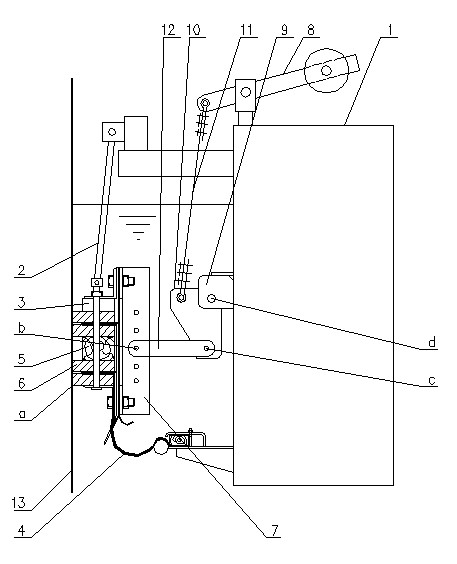
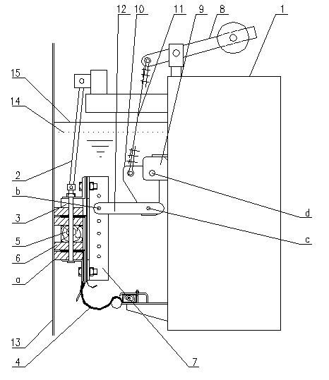
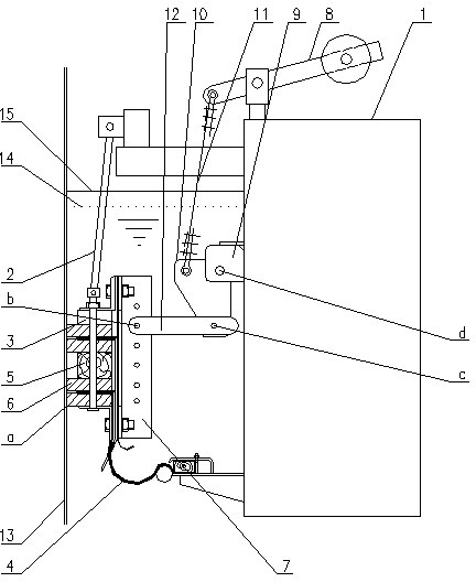
[0015] figure 2 It is a structural schematic diagram of the present invention, as shown in the figure, the cylindrical gas holder sealing device of the present invention includes two groups of sealing assemblies arranged up and down along the axis of the gas holder, and a rubber suspension mechanism fixed on the piston box beam 1 2 and a rubber pressing mechanism; the sealing assembly includes a pressing plate 3, a sealing canvas 4, a sealing rubber strip 6 separated by a clamping wood 5, and a rubber clamping mechanism 7, which are connected as a whole by a screw, and the sealing canvas 4 One end is installed between the sealing rubber strips 6, and the other end is installed on the piston box beam 1; the sealing assembly is suspended on the piston box beam 1 through the rubber suspension mechanism 2; The counterweight lever 8 connect...


PUM


Abstract

The invention discloses a cylindrical gasholder sealing device, comprising two sets of sealing assemblies arranged along an axis of a gas holder up and down, a rubber suspending mechanism fixed on a box-shaped beam of a piston, and a rubber compacting mechanism, wherein a connection rod of the rubber compacting mechanism is hinged with a rubber clamping mechanism of the sealing assemblies to ensure that a sealing rubber bar is tightly attached onto the inner wall of a cylinder sideboard; a connection line from a hinge point of the connection rod and the rubber clamping mechanism to the hinge point of the connection rod and a connection plate is horizontal, and the connection line is higher than the horizontal position of clamping a piece of splint wood. The horizontal installation position of the connection rod of the rubber compacting mechanism is increased, so that the rubber compacting mechanism horizontally applies force to the upper part of the rubber clamping mechanism for more effectively preventing the sealing assemblies from overturning towards the box-shaped beam of the piston around a contact point between the lowest edge of the sealing rubber bar and the sideboard, themaximum running speed of the piston is increased to above 3m / min (3-7m / min), and the piston can continuously run for a period.

Description

technical field [0001] The invention belongs to the technical field of sealing, and in particular relates to a sealing device for a cylindrical gas cabinet. Background technique [0002] With the development of large-scale blast furnaces in the metallurgical industry, the main user of blast furnace gas, the power plant, is also tending to be large-scale, which requires that the throughput of the gas cabinet serving the gas transmission and distribution system must be large, that is, the piston speed is fast, and it must continue to run for a period of time. Time, to ensure the time required for gas dispatching and user switching fuel, etc., to ensure the safe production and operation of the gas system and reduce the gas emission rate to the greatest extent. For example, 5000m 3 When the blast furnace suddenly shuts down, the gas tank needs to replenish about 750,000 m to the pipe network 3 Gas volume per hour, corresponding to 150,000 m 3 The piston speed of the gas holde...

Claims


Application Information

Patent Timeline
Patent Type & Authority Applications(China)
IPC IPC(8): F17B1/04
Inventor 高海平钱力王苏林程杰刘俊鹏郭鹏志柳智戴连鹏
Owner CISDI ENG CO LTD
Learn More