Automatic air locking dehydration device for gas pipeline

A gas pipeline and dehydration device technology, which is applied in the pipeline system, gas/liquid distribution and storage, mechanical equipment, etc., can solve the problems of scattered installation sites, wide distribution range, large investment, etc., and achieve reduced labor intensity and less manual maintenance , the effect of saving water resources

Inactive Publication Date: 2011-09-21
NANTONG SHENDONG METALLURGICAL MACHINERY
View PDF5 Cites 2 Cited by
  • Summary
  • Abstract
  • Description
  • Claims
  • Application Information

AI Technical Summary

Problems solved by technology

During the actual operation, it was found that: 1. Some anti-leakage gas drains malfunctioned when the gas pressure fluctuated, so that the gas drainer could not discharge the internal condensed water in time, and in serious cases, the entire overhead gas pipeline collapsed; 2. Some anti-leakage 3. When some anti-leakage gas drains are running at low pressure, once the water seal is broken down, they will not be able to prevent gas leakage.
4. Some anti-leakage gas drains must be manually restored to continue draining after sealing the gas
5. Due to the large number of drains, wide distribution and scattered installation locations, considerable personnel are required to conduct inspections, which is quite inconvenient to manage
This kind of equipment with the help of intelligent control technology not only requires a large investment, but also cannot ensure the safe operation of the gas pipeline once the electrical facilities are powered off or the components are damaged.

Method used


Image

  • Automatic air locking dehydration device for gas pipeline
  • Automatic air locking dehydration device for gas pipeline
  • Automatic air locking dehydration device for gas pipeline

Examples


Embodiment Construction

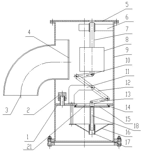
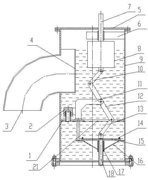
[0017] like figure 1 and 2 As shown, the gas pipeline automatic gas lock dehydration device of the present invention comprises an outer shell 9, the top of the outer shell 9 is provided with a dustproof cover 5, and the side of the outer shell 9 is provided with an overflow port 3, and the overflow port 3 is connected to the outer shell The water tank 4 in 9 is connected, the setting of the water tank 4 has improved the effective water seal height of the gas drainer 20, increased the water seal safety margin of the gas drainer 20, and the outer shell 9 inner wall below the dust cover 5 is equipped with Guide frame 6, the guide frame 6 is provided with a water level display rod 7 that runs through the outside of the dust cover 5, and the water level display rod 7 can intuitively reflect the water level in the gas drainer 20. The lower end of the water level display rod 7 and the buoy 8 The connection is fixed, the bottom of the buoy 8 is hinged to one end of the connecting rod...


PUM


Abstract

The invention relates to an automatic air locking dehydration device for gas pipeline, and the device provided by the invention comprises an outer shell, wherein the side of the outer shell is provided with an overflow gate, the overflow gate is connected with a water channel which is arranged in the outer shell, a guide frame is arranged on the inner wall of the outer shell below a dust shield, a water level indicator penetrating through the dust shield is arranged in the guide frame, the lower end of the water level indicator is fixedly connected with a float bowl, the bottom of the float bowl is articulated with one end of a connecting rod a, the other end of the connecting rod a is articulated with one end of a rotating arm, the other end of the rotating arm is articulated with one end of a connecting rod b, the other end of the connecting rod b is fixedly connected with an air locking board, the middle part of the rotating arm is articulated with one end of a rotating arm shaft lug, the other end of the rotating arm shaft lug is fixed on division boards, the division board on the left of the rotating arm shaft lug is provided with a decompression valve, the division board on the right of the rotating arm shaft lug is provided with a drainage through hole, and a guide splitter plate is arranged below the air locking board. The device provided by the invention has good effect on gas leakage prevention; and self-sufficient water charging can be realized depending on the gas pipeline self condensed water, and the self-recovery of a drainage channel is achieved by virtue of the decompression valve, thereby realizing all-weather continuous working.

Description

technical field [0001] The invention relates to an automatic gas locking and dehydrating device for a gas pipeline. Background technique [0002] The anti-leakage gas drainer in the prior art includes a gas drainer and an anti-leakage device. The anti-leakage device includes a cylinder body, an indicating rod, a baffle plate and a buoy placed in the cylinder below the baffle plate. During the actual operation, it was found that: 1. Some anti-leakage gas drains malfunctioned when the gas pressure fluctuated, so that the gas drainer could not discharge the internal condensed water in time, and in serious cases, the entire overhead gas pipeline collapsed; 2. Some anti-leakage 3. When some anti-leakage gas drains are running at low pressure, once the water seal is broken down, they will not be able to prevent gas leakage. 4. Some anti-leakage type gas drains must be manually restored to continue draining after sealing the gas. 5. Due to the large number of drains, wide distrib...

Claims


Application Information

Patent Timeline
Patent Type & Authority Applications(China)
IPC IPC(8): F17D3/14
Inventor 陈永新
Owner NANTONG SHENDONG METALLURGICAL MACHINERY
Why Eureka
Try Eureka