Circumferential magnetic conduction structure of Hall sensor
A technology of Hall sensor and circumference, which is applied in the direction of transmitting sensing components and permanent magnets with electric/magnetic devices, which can solve the problems of Hall chip magnetic field strength weak, uneven, poor magnetic permeability, etc., and achieve uniform magnetic field changes , Enhanced magnetic field strength, easy processing and forming
Inactive Publication Date: 2011-09-21
SHANGHAI SEEYAO ELECTRONICS CO LTD
View PDF6 Cites 7 Cited by
- Summary
- Abstract
- Description
- Claims
- Application Information
AI Technical Summary
Problems solved by technology
Due to the poor magnetic permeability of the magnetic field in the air, the magnetic field intensity sensed by the Hall chip will be weak and uneven
Method used
View moreImage
Smart ImageViewing Examples
Examples
Embodiment Construction
Login to View More PUM
 Abstract
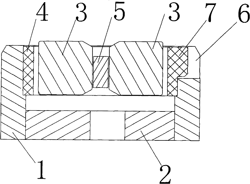
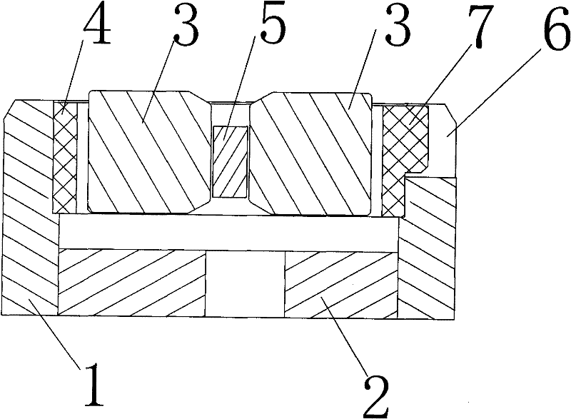
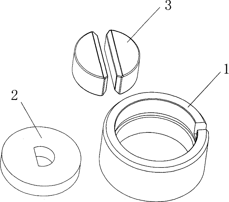
The invention provides a circumferential magnetic conduction structure of a Hall sensor. The magnetic conduction structure comprises an annular permanent magnet, a Hall chip, a circular ring sleeve and two magnetic conduction blocks, wherein the circular ring sleeve is made of a magnetic conduction material, and the annular permanent magnet is fixed on the inner wall of the circular ring sleeve; the two magnetic conduction blocks are positioned inside the annular permanent magnet, and a gap is formed between the external surfaces of the two magnetic conduction blocks and the internal surface of the annular permanent magnet; and the Hall chip is positioned between the two magnetic conduction blocks. By means of the circumferential magnetic conduction structure disclosed by the invention, a magnetic field is effectively focused at the inner side of the circular ring sleeve so that the magnetic field induced by the Hall chip is stable and has high magnetic intensity; and the circumferential magnetic conduction has the advantages of simplicity for processing and forming.
Description
Circumferential magnetic structure of Hall sensor technical field The invention relates to a magnetically conductive structure of a Hall sensor, in particular to a circumferential magnetically conductive structure of a Hall sensor. Background technique Hall sensor is a kind of magnetic sensor, which can detect the magnetic field and its changes, and it is divided into switch type, linear type and key lock type. Magnetic field sensing is an important part of the Hall sensor. The linear Hall sensor needs a uniformly changing magnetic field to ensure that the traditional linear Hall sensor only has a permanent magnet and a Hall chip. Magnets or Halls to create magnetic field changes. Due to the poor magnetic permeability of the magnetic field in the air, the magnetic field sensed by the Hall chip will be weak and uneven. Contents of the invention The technical problem to be solved by the present invention is to provide a circumferential magnetic conduction structure of a...
Claims
Login to View More Application Information
Patent Timeline
 IPC IPC(8): G01D5/12H01F7/02
Inventor 黄正辉杨晓锋王永和张东辉
Owner SHANGHAI SEEYAO ELECTRONICS CO LTD
Features
- R&D
- Intellectual Property
- Life Sciences
- Materials
- Tech Scout
- Unparalleled Data Quality
- Higher Quality Content
- 60% Fewer Hallucinations
Learn More Browse by: Latest US Patents, China's latest patents, Technical Efficacy Thesaurus, Application Domain, Technology Topic, Popular Technical Reports.
© 2025 PatSnap. All rights reserved.Legal|Privacy policy|Modern Slavery Act Transparency Statement|Sitemap|About US| Contact US: help@patsnap.com


