Urea liquid level sensor

A technology of urea sensor and urea solution, which is applied in the direction of buoy liquid level indicator, etc., can solve the problems of high cost of CAN instrument, unfavorable popularization and application, etc., and achieve the effect of reliability and stability

Inactive Publication Date: 2011-09-21
WEICHAI POWER CO LTD
View PDF5 Cites 13 Cited by
  • Summary
  • Abstract
  • Description
  • Claims
  • Application Information

AI Technical Summary

Problems solved by technology

Because the cost of CAN meters is much higher than ordinary

Method used


Image

  • Urea liquid level sensor
  • Urea liquid level sensor
  • Urea liquid level sensor

Examples


Embodiment Construction

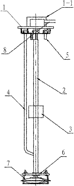
[0029] The core of the present invention is to provide a urea liquid level sensor. The sensor can avoid the interference of external factors and pressure, has very reliable stability, and can output multiple liquid level signals, and is suitable for various instruments.

[0030] In order to enable those skilled in the art to better understand the solution of the present invention, the present invention will be further described in detail below in conjunction with the accompanying drawings and specific embodiments.

[0031] The words "left, right" and other directions in this article are based on the positional relationship of the drawings, and should not be interpreted as an absolute limitation on the scope of protection.

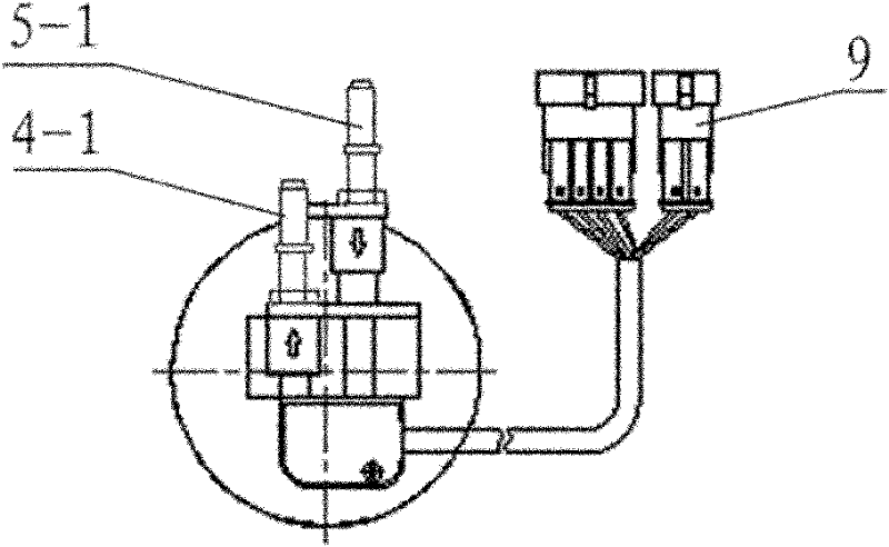
[0032] Please refer to figure 1 , figure 2 , figure 1 It is a structural schematic diagram of a specific embodiment of the urea liquid level sensor provided by the present invention; figure 2 for figure 1 Top view of the urea level sensor shown.

[...


PUM


Abstract

The invention discloses a urea liquid level sensor. The urea liquid level sensor comprises a connecting piece connected with a urea box, and a guide tube arranged on the connecting piece; a magnetic floater capable of moving up and down is sleeved outside the guide tube; a measuring circuit controlled by the magnetic floater is sealed inside the guide tube; a signal transmission line connected with the measuring circuit is arranged on the connecting piece; the measuring circuit comprises a plurality of groups of magnetic control units arranged along a length direction of the guide tube; each group of the magnetic control units comprises a resistor and a non-contact switch which are connected in series; the plurality of groups of magnetic control units are connected in parallel with one another on the circuit; and one end of the parallel circuit is a grounding end, and the other end of the parallel circuit is a signal output end. The sensor cannot be influenced by outside factors and pressure, has rather reliable stability, can output a plurality of paths of liquid level signals and is applicable to various instruments.

Description

technical field [0001] The invention relates to the technical field of diesel engines, in particular to a sensor for monitoring the urea liquid level in an SCR system of a diesel engine. Background technique [0002] Due to the characteristics of diesel and its combustion mode, compression ignition diesel engine emits much less HC and CO than gasoline engine, but emits NO x Coexist with PM in large numbers. Therefore, the focus of diesel engine emission control should be to reduce particulate matter and NO x emissions. [0003] In order to meet the emission requirements of Euro IV and above, it is difficult for diesel engines to meet the increasingly stringent emission regulations by relying on combustion improvement and other internal purification technologies alone. , Selective Catalytic Reduction) is the fastest way to realize Euro IV / V, and it is also a necessary means to realize Euro VI. At the same time, engines using SCR technology can more effectively reduce NO ...

Claims


Application Information

Patent Timeline
IPC IPC(8): G01F23/72
Inventor 孙少军佟德辉邓玉龙黄继轩潘凤文
Owner WEICHAI POWER CO LTD
Why Eureka
Try Eureka