Optical waveguide device and manufacturing method of optical waveguide device
A technology of optical waveguide and waveguide, which is applied in the direction of optical waveguide light guide, light guide, optical element, etc.
- Summary
- Abstract
- Description
- Claims
- Application Information
AI Technical Summary
Problems solved by technology
Method used
Image
Examples
no. 1 example
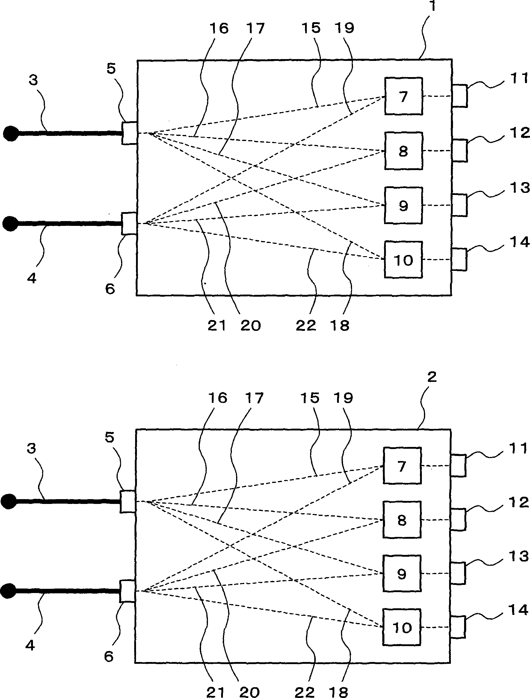
[0025] figure 1 is an exemplary diagram showing the structure of an optical waveguide device of a preferred embodiment of the present invention. Such as figure 1 As shown, the optical waveguide device is equipped with optical waveguide lines 1 and 2 . Each of the optical waveguide lines 1 and 2 has an input terminal 5 connected to the waveguide 3, and the optical signal input from the input terminal 5 is branched to optical paths 15-18, and output from sequentially arranged output terminals 11-14. In addition, each of the optical waveguide lines 1 and 2 has an input terminal 6 connected to the waveguide 4, and the optical signal input from the input terminal 6 is branched to optical paths 19-22, and output from sequentially arranged output terminals 11-14.
[0026] The optical waveguide lines 1 and 2 have optical lines, and the optical lines give the optical signals propagating along the optical paths 16-22 respectively π, π / 2, 3π / 2, 0, π, π / 2, 3π / 2 phase difference. In ...
no. 2 example
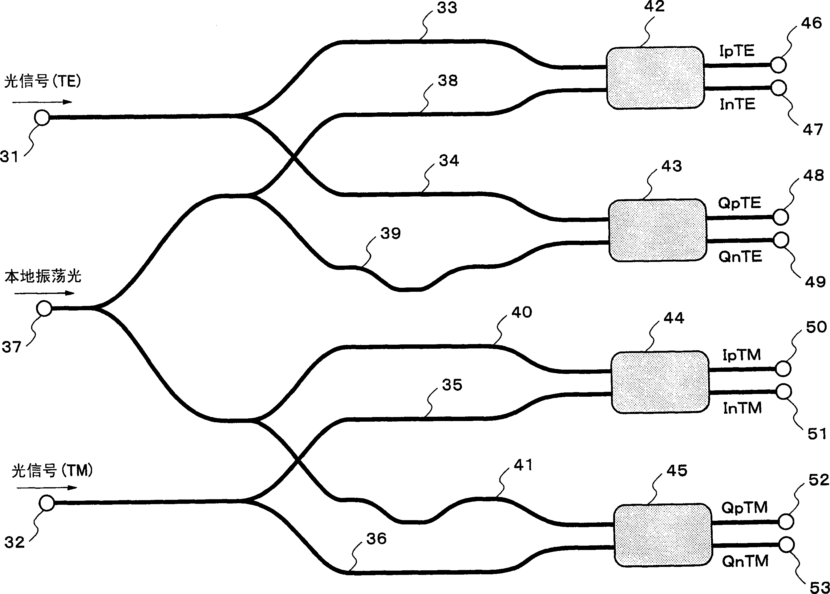
[0030] figure 2 is an exemplary diagram showing the composition of an optical waveguide of a 90° optical hybrid interferometer according to a second embodiment of the present invention. exist figure 2 Among them, the signal optical input ports 31 and 32 respectively receive TE and TM optical signals respectively having separated polarized waves. The signal optical waveguide arms 33-36 transmit TE and TM optical signals, each of which is split into two paths. The local oscillation light input port 37 receives local oscillation light, and is provided between the signal light input ports 31 and 32 . The local oscillation optical waveguide arms 38 - 41 transmit the local oscillation light branched into two paths on the TE optical signal side and the TM optical signal side and further branched into two paths respectively. The optical coupler 42 combines each pair of the signal optical waveguide arm 33 and the local oscillation optical waveguide arm 38, and outputs each pair of i...
no. 3 example
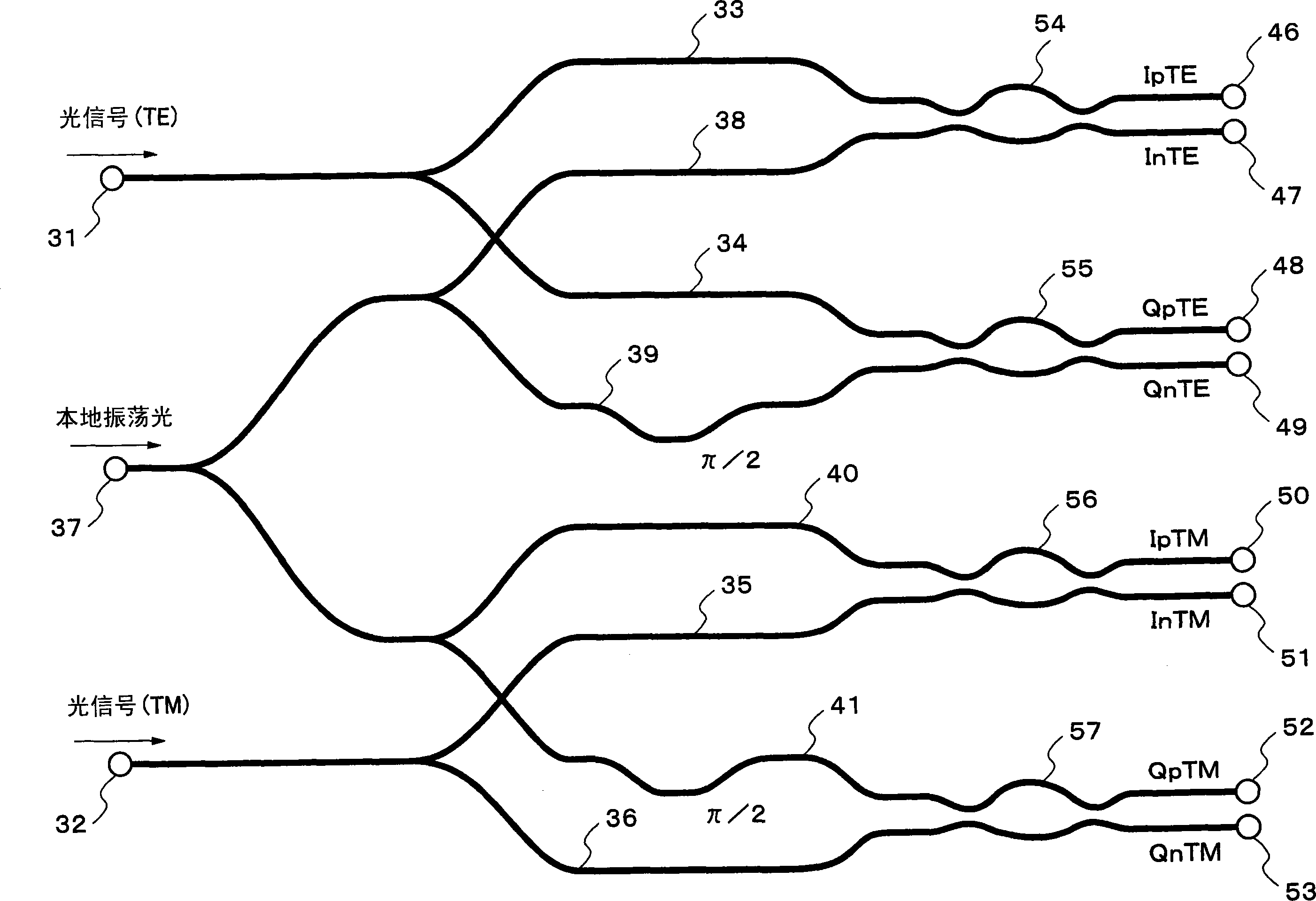
[0039] image 3 is an exemplary diagram showing the optical waveguide composition of the 90° optical hybrid interferometer of the third embodiment of the present invention. exist image 3 , use the same code to markup with figure 2 corresponding parts.
[0040] In the third embodiment, all of the Mach-Zehnder interferometers 54-57 are used as optical couplers. Also, the local oscillation optical waveguide arms that impart a π / 2 phase difference to the local oscillation light are the arm 39 and the arm 41, and all the upper optical waveguides of the Mach-Zehnder interferometers 54-57 are longer than the lower optical waveguides. As a result, the output interference characteristics of each Mach-Zehnder interferometer itself are all equal, and the phase difference according to the difference in phase conversion characteristics is zero. In addition, in the signal optical waveguides 33, 34, 35, and 36, each section (from the branching section to the optical coupler) constituti...
PUM
 Abstract
Description
Claims
Application Information
 - R&D
- Intellectual Property
- Life Sciences
- Materials
- Tech Scout
- Unparalleled Data Quality
- Higher Quality Content
- 60% Fewer Hallucinations
Browse by: Latest US Patents, China's latest patents, Technical Efficacy Thesaurus, Application Domain, Technology Topic, Popular Technical Reports.
© 2025 PatSnap. All rights reserved.Legal|Privacy policy|Modern Slavery Act Transparency Statement|Sitemap|About US| Contact US: help@patsnap.com


