Connector

一种凹型连接器、插入式连接器的技术,应用在连接、固定连接、两部件连接装置等方向,能够解决高频信号屏蔽效果下降、串扰增大等问题,达到构造简单、减小串扰、容易装配的效果

Active Publication Date: 2011-09-21
YAMAICHI ELECTRONICS
View PDF5 Cites 8 Cited by
  • Summary
  • Abstract
  • Description
  • Claims
  • Application Information

AI Technical Summary

Problems solved by technology

As a result, the shielding effect of each ground contact against high-frequency signals with frequency components of several GHz is reduced.
As a result, there may be a problem of increased crosstalk between adjacent signal line contacts or increased crosstalk between signal line contacts separated by one contact.

Method used


Image

  • Connector
  • Connector
  • Connector

Examples


no. 1 example

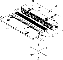
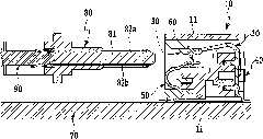
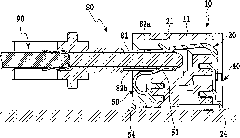
[0032] Figure 1 to Figure 7 The first embodiment of the in-line connector of the present invention is shown. In addition, in the description of this embodiment, "left" and "right" refer to figure 1 In the +x direction and -x direction, "front" and "rear" refer to the +y and -y directions, respectively, and "up" and "down" refer to the +z and -z directions, respectively.

[0033] Such as Figure 1 to Figure 7 As shown, the direct plug-in connector 10 of the first embodiment of the present invention is mounted on a first printed circuit board 70 . In addition, the plug connector 80 inserted into the in-line connector 10 is mounted on the second printed circuit board 90 . The plug connector 80 is plugged into the plug-in connector 10 . Specifically, the blade 81 of the plug connector 80 is inserted into the plug connector accommodation space 19 a of the direct plug-in connector 10 . As a result, the first pad 82a and the second pad 82b as external contacts respectively arra...

no. 2 Embodiment

[0067] Figure 8 ~ Figure 14 A second embodiment of the direct plug-in connector of the present invention is shown. The structure of the common contact of this embodiment is different from the structure of the common contact of the above-mentioned first embodiment. The structure of the first signal line contact and the first ground contact and the connection between the first ground contact and the common contact The connection structure of the head connection is also different. The following description will focus on the differences between the second embodiment and the first embodiment. Also in this embodiment, as in the first embodiment described above, only the contacts for the first signal line are used for high-speed signal transmission.

[0068] In addition, in the description of this embodiment, "left" and "right" refer to Figure 8 In the +x direction and -x direction, "front" and "rear" refer to the +y and -y directions, respectively, and "up" and "down" refer to ...


PUM


Abstract

The present invention provides a card edge connector as a high-speed differential signal connector configured to equalize electric potentials of ground contacts adjacent to signal line contacts, and thus to reduce crosstalk between adjacent signal line contacts. The card edge connector serves as a female connector in which multiple signal line contacts and multiple ground contacts are arranged inparallel in at least one row. In the card edge connector, the signal line contacts and the ground contacts are arranged in a way that every two signal line contacts for high-speed signals to send andreturn respectively therethrough are interposed between two ground contacts, and all of the multiple ground contacts arranged in the one row are electrically connected to one another by use of a common contact.

Description

technical field [0001] The present invention relates to a card edge connector as a female connector disposed on a printed circuit board or the like, and more particularly to a card edge connector having a structure for reducing crosstalk. Background technique [0002] Conventionally, for example, as shown in Japanese Patent Application Laid-Open No. 2007-149643, there is known a prior art in which a plug connector (Plug connector) as a male connector (male connector) is provided on one printed circuit board, On the other printed circuit board, a direct plug-in connector as a female connector is provided to electrically connect the printed circuit boards to each other. [0003] In such a connector, in order to suppress crosstalk, the arrangement of contacts is preferably a coplanar structure in which ground contacts (G) interpose round-trip signal contacts (S), that is, a G-S-S-G arrangement. [0004] However, in recent years, with the increase in speed of signal transmissio...

Claims


Application Information

Patent Timeline
Patent Type & Authority Applications(China)
IPC IPC(8): H01R13/6471H01R13/02H01R12/51
CPCH01R24/38H01R12/721H01R13/6471H01R12/737H01R13/6474
Inventor 伊东利育茎田启明
Owner YAMAICHI ELECTRONICS
Why Eureka
Try Eureka