Control apparatus for electric rotating machine

一种控制设备、旋转电机的技术,应用在电动发电机控制、交流电动机控制、电子换向电动机控制等方向,能够解决不准确等问题,达到减少改变次数的效果

Inactive Publication Date: 2011-09-21
DENSO CORP
View PDF6 Cites 6 Cited by
  • Summary
  • Abstract
  • Description
  • Claims
  • Application Information

AI Technical Summary

Problems solved by technology

Therefore, the conventional control devices described above do not always sufficiently reduce the number of switching state changes
Furthermore, since the accuracy of the torque prediction by extrapolation is not necessarily high, accordingly the conventional control apparatus described above variably sets the weighting factors for evaluating the number of changes of the switch state based on the inaccurate torque behavior prediction , so there is a problem with the reliability of the control

Method used


Image

  • Control apparatus for electric rotating machine
  • Control apparatus for electric rotating machine
  • Control apparatus for electric rotating machine

Examples


no. 1 example

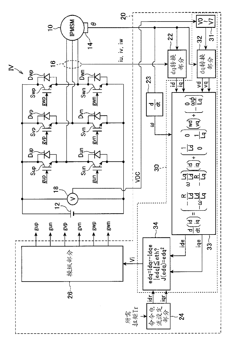
[0030] figure 1 is a diagram showing the overall structure of a control system for controlling a motor / generator 10 mounted on a hybrid vehicle, the control system including the control device 20 according to the first embodiment of the present invention. Motor / generator 10 is a three-phase permanent magnet synchronous motor. The motor / generator 10 is also a rotating electrical machine with salient poles. That is, the motor / generator 10 is an IPSM (Interior Permanent Magnet Synchronous Motor).

[0031] The motor / generator 10 is connected to a high voltage battery 12 through an inverter IV. The inverter IV includes a series connection of switching elements Sup and Sun, a series connection of switching elements Svp and Svn, and a series connection of switching elements Swp and Swn. These series-connected connection nodes are respectively connected to the U-phase, V-phase and W-phase windings of the motor / generator 10 . As each of the switching elements Sup, Sun, Svp, Svn, Sw...

no. 2 example

[0093] Next, a second embodiment of the present invention will be described, wherein the differences from the first embodiment will be particularly emphasized.

[0094] Figure 13 is a flowchart showing the operation of the model predictive control performed in the second embodiment. The operations are repeatedly performed by the control device 20 at regular time intervals. exist Figure 13 in, with Image 6 The same step numbers shown in represent the same steps.

[0095] The operation differs from the equivalent operation of the first embodiment in the condition for setting the state transition permission flag F to 1. The condition in the first embodiment is that the magnitude relationship between the norm |Idqr| of the command current vector Idqr and the norm |Idqe| of the predicted current vector Idqe is reversed. But in the second embodiment, the condition is that the end point of the error vector edq whose starting point is at the origin reaches a straight line ( ...

no. 3 example

[0098] Next, a third embodiment of the present invention will be described, in which differences from the first embodiment will be particularly emphasized.

[0099] Figure 15 is a flowchart showing the operation of the model predictive control performed in the third embodiment. The operations are repeatedly performed by the control device 20 at regular time intervals. exist Figure 15 in, with Image 6 The same step numbers shown in represent the same steps.

[0100] The operation differs from the equivalent operation of the first embodiment in the manner in which the average voltage vector Va is calculated. In a second embodiment, the average voltage vector Va is calculated in step S16a by calculating a simple moving average of the voltage vectors V(n), V(n-1), ... V(n-N), where the voltage vector V (n), V(n−1), . . . V(n−N) represent operation states respectively adopted at past N (>2) update timings up to the previous update timing. Since the period of the control cy...


PUM


Abstract

The control apparatus for an electric rotating machine includes a prediction section to predict a controlled variable of the electric rotating machine applied with an output voltage of a power conversion circuit for each of prescribed operation states of the power conversion circuit, and a manipulation section to manipulate the power conversion circuit to operate in one of the respective operation states determined as an actual operation state based on the controlled variable predicted by the prediction section. The control apparatus further includes an average voltage direction calculating section to calculate a direction of an average output voltage vector of the power conversion circuit. The manipulation section includes a priority setting section to set priority for each of the operation states based on the direction of the average output voltage vector calculated by the average voltage direction calculating section in determining the actual operation state.

Description

technical field [0001] The invention relates to a control device for a rotating electrical machine. Background technique [0002] As described in, for example, Japanese Patent Application Laid-Open No. 2006-174697, there is known a control apparatus that performs model predictive control in order to control a rotating electric machine. The control device operates as follows. First, the switching state sequence at sampling timings k, k+1, . Next, prediction of the subsequent torque trace is performed by extrapolation as the torque trace at sampling timings k+N−1 to k+N. Next, the number of times of change of the switch state in the provisional setting sequence is divided by the number n representing the number of sampling times performed until the torque predicted by the extrapolation deviates from a predetermined range. Next, if the quotient of the preceding division is the minimum value of all provisionally set switching sequences, the switching state at sampling timing ...

Claims


Application Information

Patent Timeline
Patent Type & Authority Applications(China)
IPC IPC(8): H02P21/14H02P27/06H02M7/48H02P21/00H02P21/13H02P21/18H02P21/22H02P21/24H02P23/14H02P27/04
CPCH02P6/14H02P21/0003H02P21/0035H02P27/08H02M7/53873H02P21/22
Inventor 井村彰宏
Owner DENSO CORP
Why Eureka
Try Eureka