
Locating method for phase jitter problem of satellite-borne SAR (Synthetic Aperture Radar) transmitting-receiving link

A phase jitter and link technology, applied in the direction of reflection/re-radiation of radio waves, utilization of re-radiation, measurement devices, etc., can solve the problems of jitter, failure of single-machine positioning, and phase stability index deterioration.

Inactive Publication Date: 2019-12-20
INST OF ELECTRONICS CHINESE ACAD OF SCI
View PDF0 Cites 0 Cited by
  • Summary
  • Abstract
  • Description
  • Claims
  • Application Information

AI Technical Summary

Problems solved by technology

However, in the integration test stage of the transceiver link, the main phase history corresponding to the main transceiver link and the standby phase history corresponding to the backup transceiver link both have jitter problems, and the phase stability index deteriorates to 2°, which does not meet the requirements of spaceborne SAR interferometric imaging. needs
[0005] Moreover, the integrated test method of the transceiver link in the related art cannot locate the faulty single machine that causes the phase history jitter problem

Method used


Image

  • Locating method for phase jitter problem of satellite-borne SAR (Synthetic Aperture Radar) transmitting-receiving link
  • Locating method for phase jitter problem of satellite-borne SAR (Synthetic Aperture Radar) transmitting-receiving link
  • Locating method for phase jitter problem of satellite-borne SAR (Synthetic Aperture Radar) transmitting-receiving link

Examples


Embodiment Construction

[0062] The technical solutions of the present invention will be further described in detail below in conjunction with the accompanying drawings and specific embodiments.

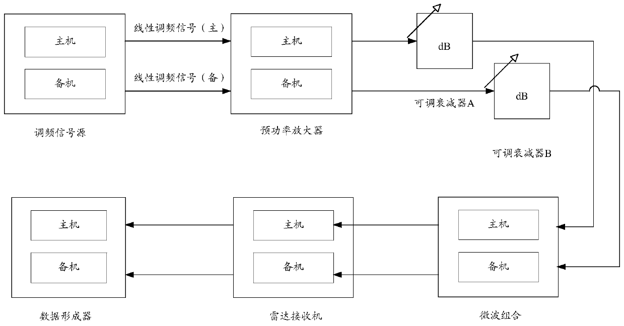
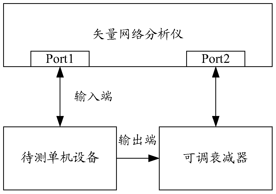
[0063] In various embodiments of the present invention, the location of the phase jitter problem is carried out under the integrated test state of the transceiver link of the spaceborne SAR, and the single-machine connection relationship in the main transceiver link (or standby transceiver link) is unchanged. , complete the problem location of the master (or standby) of the three stand-alone machines (pre-power amplifier, microwave combination, and radar receiver), and then in the state where the connection relationship of the stand-alone in the standby transceiver link (or main transceiver link) remains unchanged , complete the problem location of the standby machine (or main machine) of the three stand-alone machines, and locate the faulty single machine by comparing the phase history of the two transceiver...


PUM


Abstract

The invention discloses a locating method for the phase jitter problem of a satellite-borne SAR (Synthetic Aperture Radar) transmitting-receiving link. The method comprises the following steps of: acquiring a first master phase history corresponding to a first master transmitting-receiving link of a first transmitting-receiving link and a first standby phase history corresponding to a first standby transmitting-receiving link of the first transmitting-receiving link, wherein the first transmitting-receiving link is formed by connecting a frequency modulated signal source, a pre-power amplifier, an adjustable attenuator, a microwave combination, a radar receiver, and a data former; firstly determining whether main engines, which constitute corresponding single machines of the first master transmitting-receiving link, in the first master transmitting-receiving link have a fault; and after the fault detection of the first master transmitting-receiving link is completed, determining whether standby engines, which constitute corresponding single machines of the first standby transmitting-receiving link, in the first standby transmitting-receiving link have a fault. According to the technical scheme, the method can be used for locating a faulty single machine causing the phase jitter problem of the satellite-borne SAR transmitting-receiving link, and reducing the number of change ofthe connection state of the transmitting-receiving link in the positioning process of the faulty single machine, and saves operating time.

Description

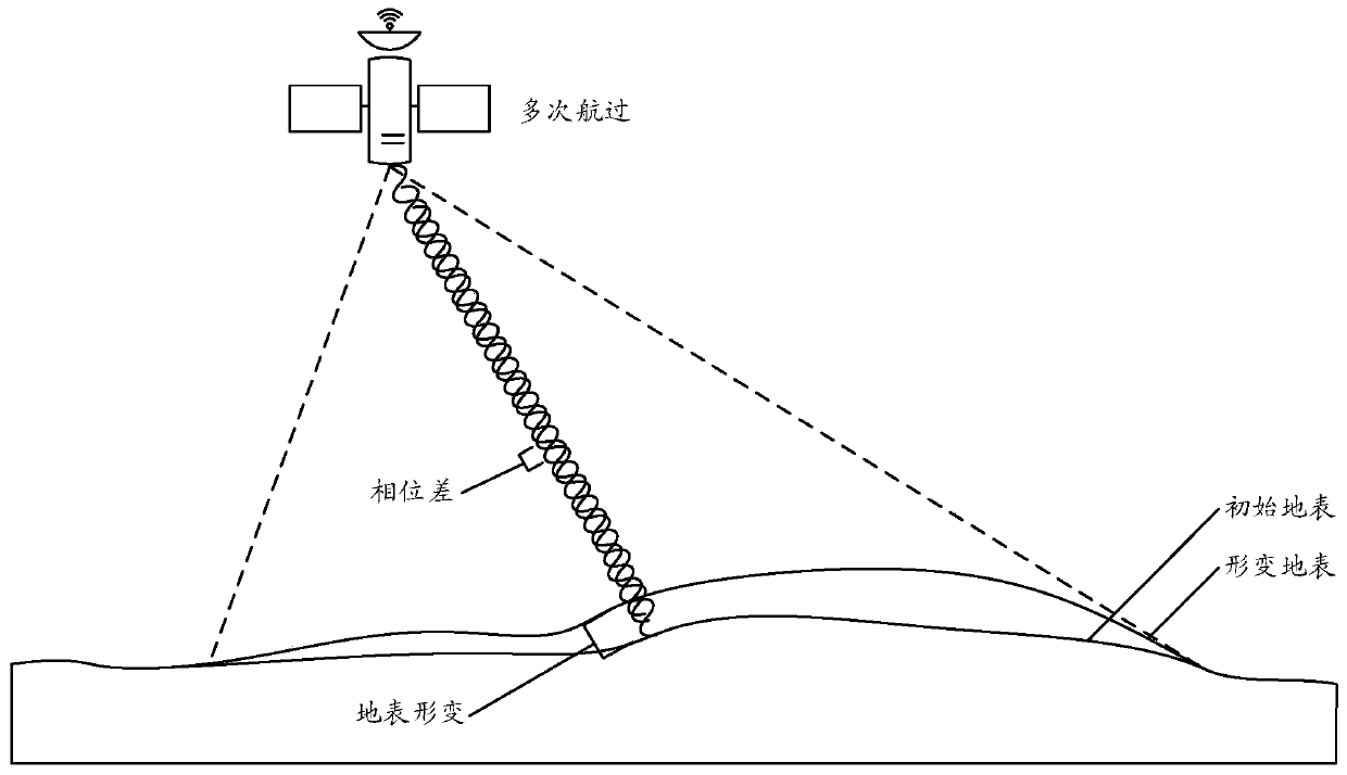
technical field [0001] The invention relates to the field of radar microwave remote sensing, in particular to a method for locating the phase jitter problem of a spaceborne Synthetic Aperture Radar (SAR, Synthetic Aperture Radar) transceiver link. Background technique [0002] Bistatic spaceborne SAR is a technology that uses formation satellites to form a baseline and obtain surface elevation information through interferometric processing. Double stars fly alone or in formation repeatedly, and the three-track method is used to obtain the surface deformation. Specifically, such as figure 1 As shown, the satellite has passed the same target area many times and made multiple observations on the same target area for a long time. Using the phase information contained in the obtained SAR complex image sequence, the advanced signal processing method is used to obtain the Accurate deformation information on the surface that occurs. Interferometric imaging processing is sensitive...

Claims


Application Information

Patent Timeline
IPC IPC(8): G01S13/90G01S7/40
CPCG01S7/4004G01S13/9023G01S13/90
Inventor 矫远波刘开雨王宇
Owner INST OF ELECTRONICS CHINESE ACAD OF SCI
Learn More