Two-degree-of-freedom (two-DOF) spherical parallel robot bionic ankle joint with central spherical pair

A spherical pair and degree of freedom technology, applied in the direction of manipulators, manufacturing tools, joints, etc., can solve the problems of low level of bionics in form and function, incomplete limb functions, reduced driving ability, etc., to improve limb coordination and posture transformation capabilities , Improving the driving ability of the limbs and the effect of improving the stability of the movement

Inactive Publication Date: 2013-06-05
YANSHAN UNIV
View PDF3 Cites 0 Cited by
  • Summary
  • Abstract
  • Description
  • Claims
  • Application Information

AI Technical Summary

Problems solved by technology

This series configuration is relatively easy to realize in terms of control, and has a simple structure, but there are serious defects: the weight of the lower-level driver often becomes the load of the upper-level driver, thereby reducing the driving capacity; 1. Ankle joint, its movement function is only equivalent to that of human beings in a few specific directions (driver axis), and there are obvious decomposition movements in other directions, and its flexibility, accuracy and stability are far behind human beings; The series joints of the kinematic pair occupy a large space and have low stiffness; the functions of the limbs are not complete, and it is not ideal for reasonably compensating the movement, adjusting the balance of the robot, completing the attitude change, and ensuring the stability of the robot's operation.
[0005] The configuration of existing humanoid robots is mainly in a single series form, and some limited parallel joints are unsatisfactory in terms of complex structure, performance, and technical indicators. The gap can not fully meet the actual needs

Method used


Image

  • Two-degree-of-freedom (two-DOF) spherical parallel robot bionic ankle joint with central spherical pair

Examples


Embodiment Construction

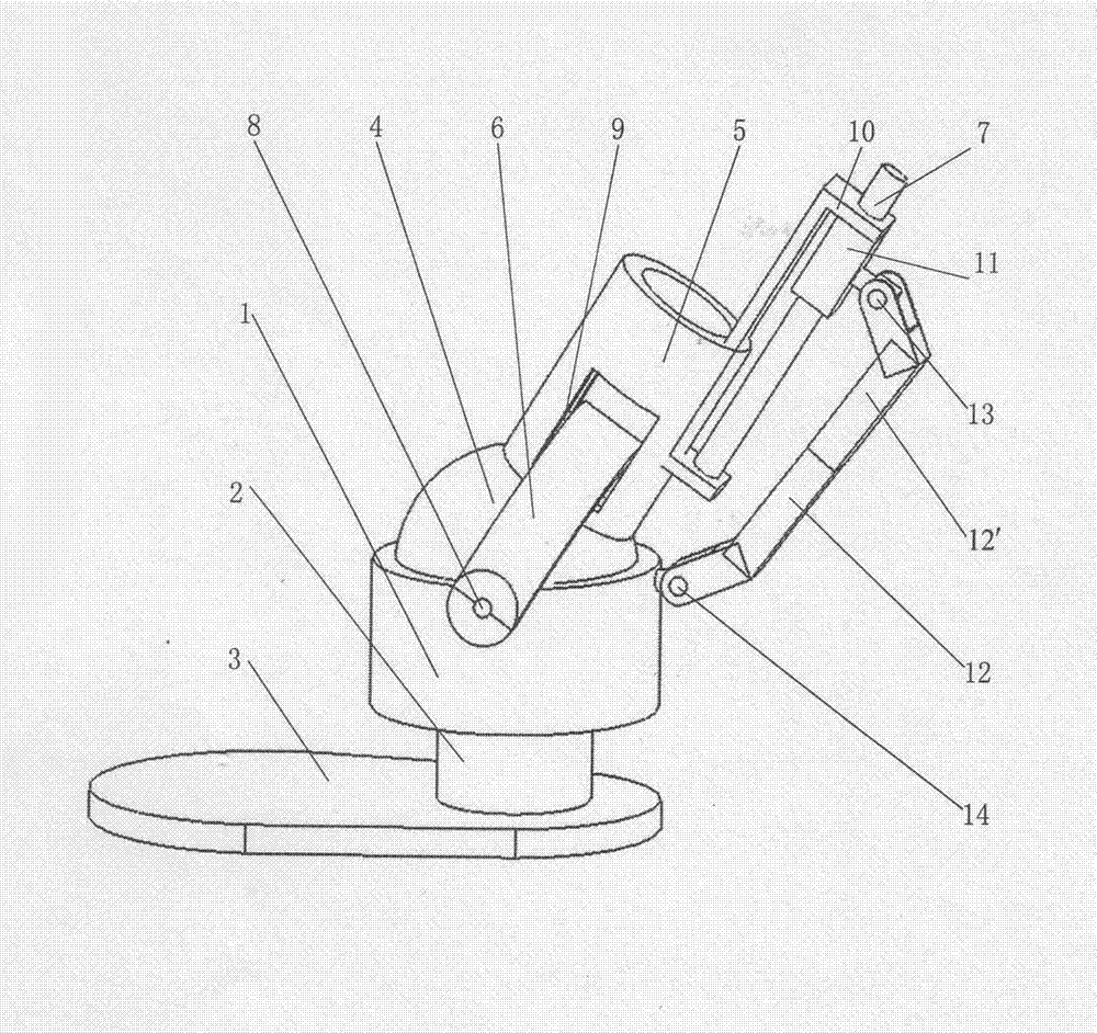
[0012] exist figure 1 In the three-dimensional schematic diagram of the bionic ankle joint with two degrees of freedom spherical parallel connection with a central spherical pair, the supporting hemispherical socket 1 is a revolving body with a concave spherical surface and the center of the ball is on the axis of rotation. perpendicular to the axis of rotation. The lower end surface of the supporting hemispherical socket is fixedly connected with the upper end of the cylindrical straight output rod 2, the axis of the straight output rod passes through the center of the supporting hemispherical socket and coincides with the rotation axis of the supporting hemispherical socket, and the lower end of the straight output rod is fixed to the upper end surface of the foot plate 3. couplet. A ball head 4 is provided in the concave spherical surface supporting the hemispherical socket, and the centers of the two overlap to form a spherical pair. The upper part of the ball head is fix...


PUM


Abstract

The invention discloses a two-degree-of-freedom (two-DOF) spherical parallel robot bionic ankle joint with a central spherical pair. The bionic ankle joint is mainly characterized in that: a straight output rod is fixed below a supporting hemispherical nest, a bulb is arranged in the straight output rod, the upper part of the bulb is connected with a columnar body bracket push rod, and the push rod is provided with a through hole, the section of which is rectangular; an outer tooth semicircular fork passes through the through hole, and the lower end of the outer tooth semicircular fork is connected with the supporting hemispherical nest; two ends of a supporting roller are placed in the through hole of the body bracket push rod, and the supporting roller is contacted with the circular inner surface of the semicircular fork; a support is arranged outside the body bracket push rod, a lead screw is arranged on the support, and a sliding block is arranged on the lead screw; the sliding block is connected with the upper end of a pull rod through an upper composite hinge fork frame; the upper composite hinge fork frame is connected with the upper end of the pull rod; and the lower end of the pull rod is connected with the outer wall of the supporting hemispherical nest through a lower composite hinge fork frame. The structure is simple and compact, and the motion of limbs is faster,flexible, smooth and continuous, so that the shape, the structure, the motion, the mechanics and the function of the bionic ankle joint are furthest close to the actual conditions of the human beings.

Description

technical field [0001] The invention relates to a humanoid robot, in particular to a bionic ankle joint of a humanoid robot. Background technique [0002] At present, people have developed a large number of various humanoid robots all over the world. Examining the existing humanoid robots, it is found that their body configurations are almost all serial configurations, that is, the multi-degree-of-freedom joints of the robot are composed of multiple single rotating pairs (or moving pairs) connected in series. This series configuration is relatively easy to realize in terms of control, and has a simple structure, but there are serious defects: the weight of the lower-level driver often becomes the load of the upper-level driver, thereby reducing the driving capacity; 1. Ankle joint, its movement function is only equivalent to that of human beings in a few specific directions (driver axis), and there are obvious decomposition movements in other directions, and its flexibility...

Claims


Application Information

Patent Timeline
Patent Type & Authority Patents(China)
IPC IPC(8): B25J17/02
Inventor 鹿玲李波周玉林
Owner YANSHAN UNIV
Why Eureka
Try Eureka