
Pneumatic spinning device and spinning machine

A technology of air spinning and rotating air flow, which is applied to spinning machines, open-end spinning machines, and continuous winding spinning machines. Problems such as small road width

Active Publication Date: 2011-09-28
MURATA MASCH LTD
View PDF10 Cites 2 Cited by
  • Summary
  • Abstract
  • Description
  • Claims
  • Application Information

AI Technical Summary

Problems solved by technology

As a result, the fiber bundle cannot be guided in the inversion chamber, and the suction flow rate in the suction decompression chamber is reduced.
On the other hand, even in the case of S=1.3D, considering the expansion of the jet flow in the swirling chamber, the flow path width of the swirling chamber is small relative to the diameter of the nozzle outlet

Method used


Image

  • Pneumatic spinning device and spinning machine
  • Pneumatic spinning device and spinning machine
  • Pneumatic spinning device and spinning machine

Examples


Embodiment Construction

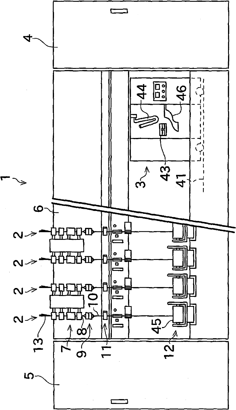
[0027] Next, a first embodiment of the present invention will be described with reference to the drawings. figure 1 The illustrated spinning machine 1 as a spinning machine includes a plurality of spinning units 2 arranged in parallel. The spinning machine 1 includes: a yarn splicing cart 3 , a blower box 4 , and a motor box 5 . The above-mentioned piecing cart 3 can travel in the direction in which the spinning units 2 are arranged.

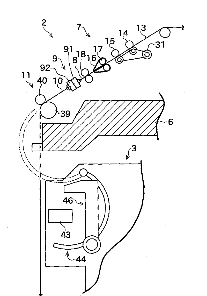
[0028] Such as figure 1 As shown, each spinning unit 2 includes, as main components, a draft device 7 , an air spinning device 9 , a yarn feeding device (drawing device) 11 , and a winding device (winding device) 12 . The draft device 7 is provided on the upper portion of the frame 6 of the spinning machine 1 . The air spinning device 9 spins the fiber bundle 8 sent from the draft device 7 to produce a spun yarn 10 . The spun yarn 10 produced in the air spinning device 9 is drawn out from the air spinning device 9 by the yarn feeding devic...


PUM


Abstract

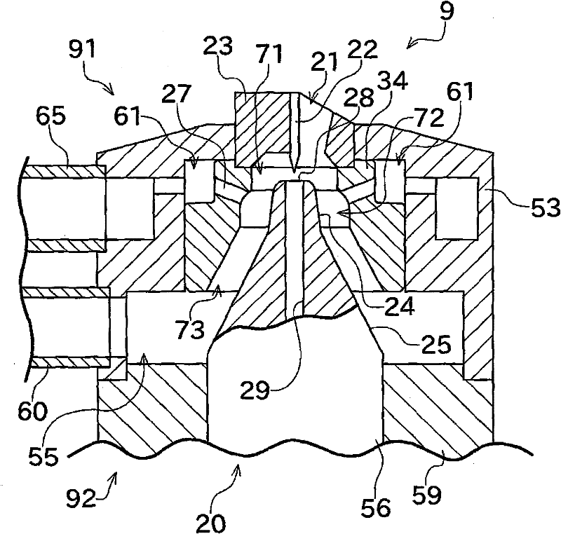
A pneumatic spinning device includes a hollow guide shaft (20), and a nozzle block (34). A portion of the hollow guide shaft (20) is located within a whirling chamber. A whirling chamber is formed in the nozzle block (34). Four air injecting nozzles (27) that inject compressed air from a nozzle opening (27a) opening into the whirling chamber to generate whirling airflow in the whirling chamber are formed in the nozzle block (34). The whirling chamber has a columnar portion formed as a substantially columnar shape having a constant diameter (D2). A height (H1) of the whirling chamber is equal to or smaller than the diameter (D2). A flow path cross-sectional area at a downstream end of the whirling chamber in a fiber feeding direction (a position A2) is formed smaller than a flow path cross-sectional area of the whirling chamber at a position where the nozzle opening (27a) is formed.

Description

technical field [0001] The present invention mainly relates to an air spinning device, and more particularly to the shape of a whirling chamber as a space for generating whirling air in the air spinning device. Background technique [0002] Conventionally, a known spinning machine includes an air spinning device that twists fibers using a swirling air flow to generate spun yarns. This air spinning device includes a whirling chamber and an air injection nozzle that generates whirling airflow in the whirling chamber by injecting compressed air into the whirling chamber. The fibers subjected to the swirling airflow are swirled in the swirling chamber, twisting is applied to the fibers, and a spun yarn is produced. [0003] In this way, since the fibers are twisted by the swirling airflow to form a spun yarn, the quality of the spun yarn is largely influenced by the flow pattern of the swirling airflow. Therefore, conventionally, great efforts have been made on the shape of th...

Claims


Application Information

Patent Timeline
IPC IPC(8): D01H4/02
CPCD01H4/02D01H1/115
Inventor 森秀茂
Owner MURATA MASCH LTD
Learn More