
Drawn composite fiber, non-woven fabric, and method of producing drawn composite fiber

a composite fiber and non-woven fabric technology, applied in the direction of fibre treatment, filament/thread forming, melt spinning methods, etc., can solve the problems of deterioration of the appearance of processed non-woven fabrics, deterioration of the processability of non-woven fabrics, and breakage of single yarns, so as to increase the thermal shrinkage and enhance the single yarn strength

Pending Publication Date: 2022-01-20
UBE NITTO KASEI CO LTD
View PDF0 Cites 0 Cited by
  • Summary
  • Abstract
  • Description
  • Claims
  • Application Information

AI Technical Summary

Benefits of technology

The invention improves the strength of a finely-drawn composite fiber without increasing its thermal shrinkage. This means that the fiber can have a stronger yarn while maintaining its shape and durability.

Problems solved by technology

However, such an increase in draw magnification has problems of resulting in yarn breakage in drawing, the deterioration of non-woven fabric processability, caused by an increase in the thermal shrinkage of drawn fibers, and the deterioration of the appearance of a processed non-woven fabric.

Method used

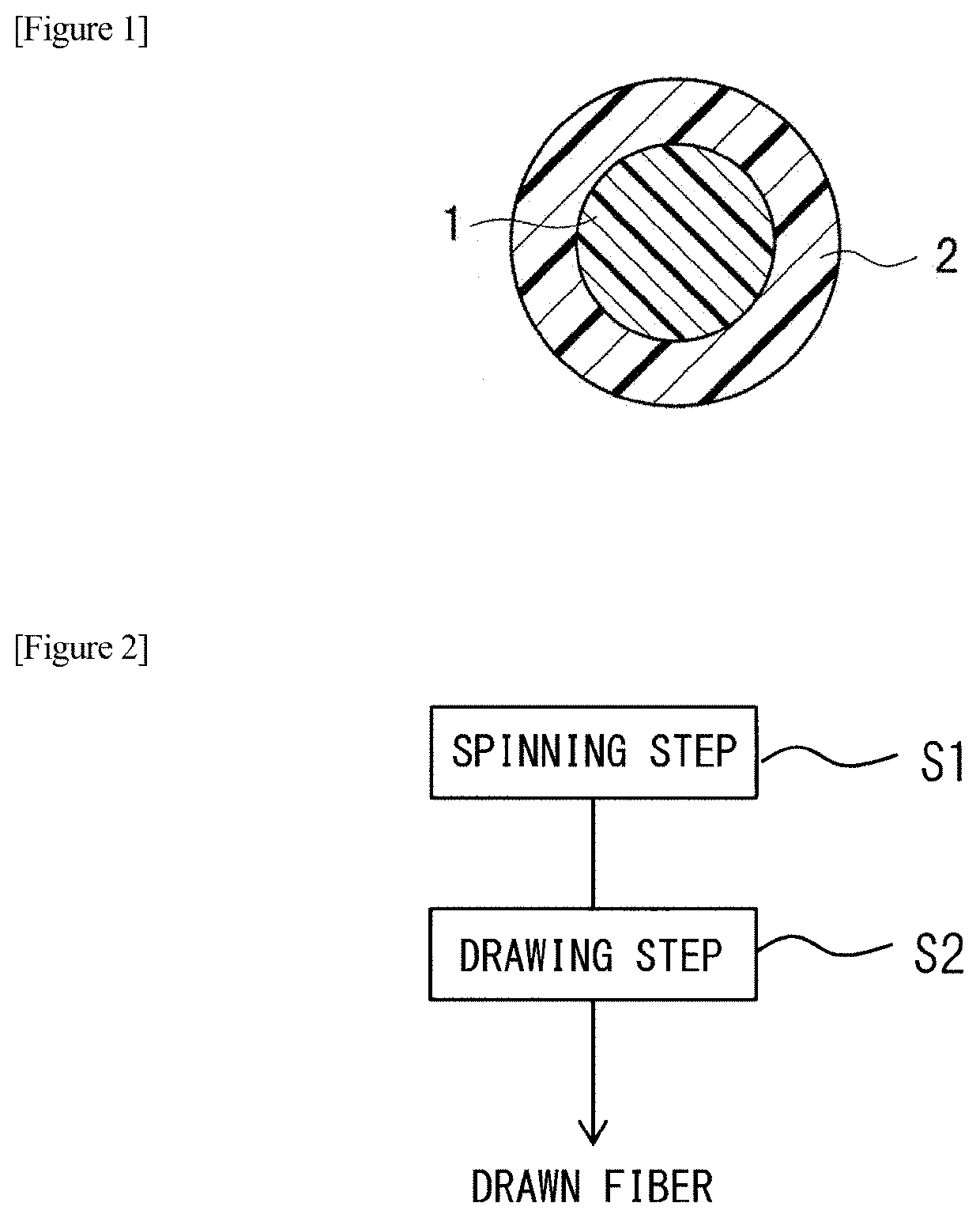

Image

  • Drawn composite fiber, non-woven fabric, and method of producing drawn composite fiber
  • Drawn composite fiber, non-woven fabric, and method of producing drawn composite fiber
  • Drawn composite fiber, non-woven fabric, and method of producing drawn composite fiber

Examples


example 1

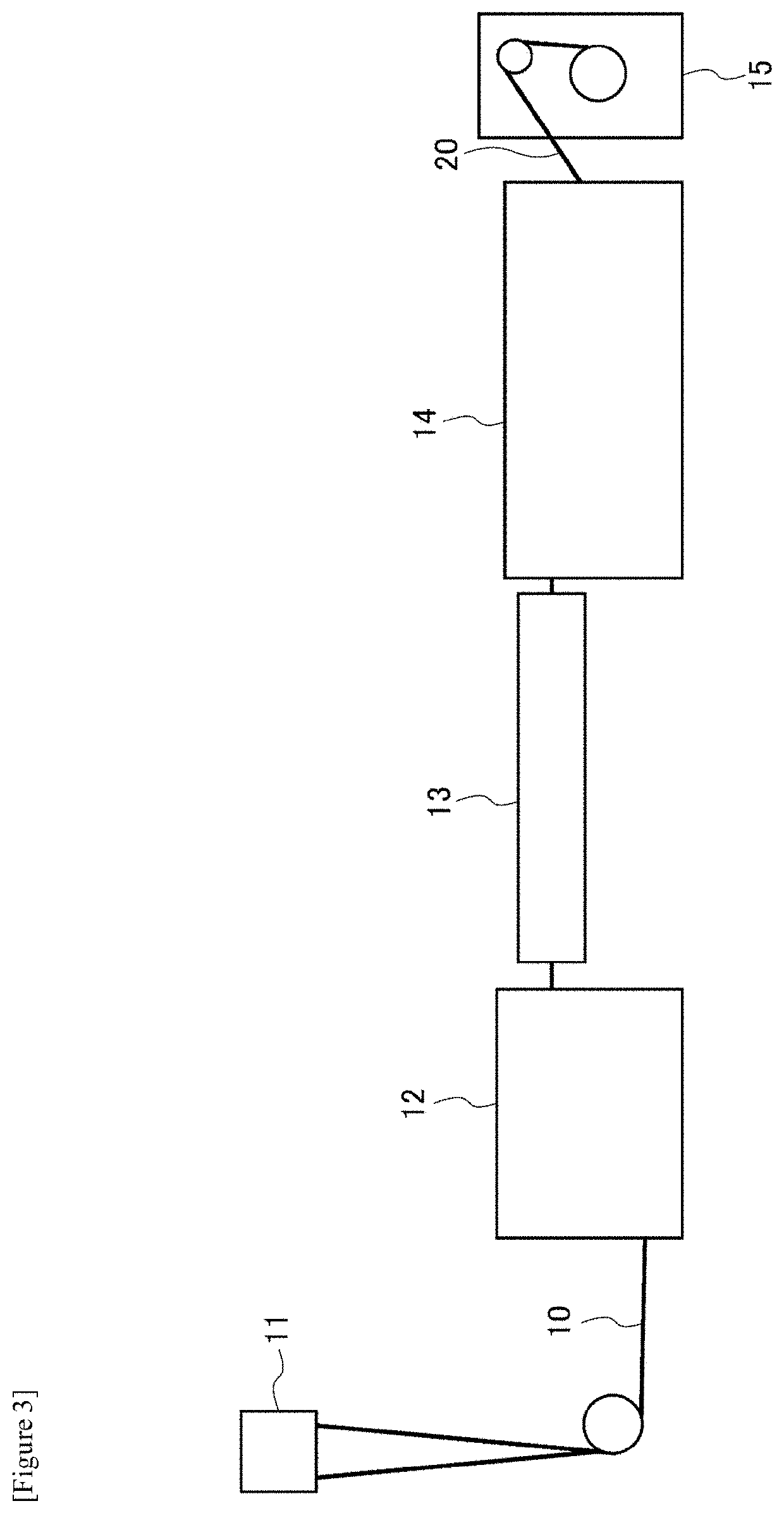
[0078]The spinning step and the drawing step were consecutively performed using the apparatus illustrated in FIG. 3, to produce a drawn composite fiber having a sheath-core structure.

[0079](1) Spinning Step

[0080]An undrawn fiber with a sheath-core structure having a fineness of 1.88 dtex was produced by melt-spinning using a core material A and a sheath material a. In such a case, a sheath-core-type composite spinneret was used, and a sheath-core ratio (sheath material / core material) was set at 35 / 65. As spinning conditions, extruder cylinder temperature was set at 255° C., spinneret temperature was set at 270° C., and a spinning speed was set at 180 m / min.

[0081](2) Drawing Step

[0082]The drawing step was performed subsequently to the spinning step. Specifically, the undrawn fiber 10 obtained in the spinning step was introduced into the introduction roller 12 at a speed of 180 m / min, the speed of the drawn fiber delivery roller 14 was increased, and the undrawn fiber 10 was drawn in ...

example 2

[0084]An undrawn fiber having a fineness of 1.72 dtex was melt-spun by a method and under conditions similar to those in Example 1 except that a core material B was used instead of the core material A, and a sheath-core ratio (sheath material / core material) was set at 25 / 75, and the undrawn fiber was drawn by a method and under conditions similar to those in Example 1.

[0085]As a result, the speed of a drawn fiber delivery roller 14 and a draw magnification, at which yarn breakage did not occur in a spinning step and a drawing step, and it was possible to perform industrially stable drawing, were 841 m / min and 4.67 times, respectively. Moreover, the fineness of a drawn composite fiber of Example 2 produced under such conditions was 0.4 dtex.

example 3

[0086]An undrawn fiber having a fineness of 1.60 dtex was melt-spun by a method and under conditions similar to those in Example 1 except that a sheath-core ratio (sheath material / core material) was set at 50 / 50, and the undrawn fiber was drawn by a method and under conditions similar to those in Example 1.

[0087]As a result, the speed of a drawn fiber delivery roller 14 and a draw magnification, at which yarn breakage did not occur in a spinning step and a drawing step, and it was possible to perform industrially stable drawing, were 781 m / min and 4.34 times, respectively. Moreover, the fineness of a drawn composite fiber of Example 3 produced under such conditions was 0.4 dtex.


PUM

PropertyMeasurementUnit
melt flow rateaaaaaaaaaa
thermal shrinkageaaaaaaaaaa

Abstract

Embodiments relate to a drawn composite fiber having a low thermal shrinkage, and a high single yarn strength, a non-woven fabric using the same, and a method of producing the same. The drawn composite fiber has a fineness of 0.6 dtex or less, a ratio between the cross-sectional areas of a sheath material and a core material (sheath material / core material) of 50 / 50 to 10 / 90, and a single yarn elastic modulus of 70 cN / dtex or more. The drawn composite is obtained by melt-spinning and a drawing treatment of an undrawn fiber having a sheath-core structure, in which the core material includes a resin containing a crystalline propylene-based polymer and having a melt flow rate of 10 to 30 g / 10 min at a load of 21.18 N at 230° C., and the sheath material includes a resin containing an olefinic polymer where the melting point is lower than that of the core material.

Description

RELAYED APPLICATIONS[0001]The present application is a National Phase of International Application No. PCT / JP2020 / 011925 filed Mar. 18, 2020, which claims priority to Japanese Application No. 2019-068001, filed Mar. 29, 2019.TECHNICAL FIELD[0002]The present invention relates to a drawn composite fiber having a sheath-core structure, a non-woven fabric, and a method of producing the drawn composite fiber. More specifically, the present invention relates to a drawn composite fiber having a thin fineness of 0.6 dtex or less, a method of producing the drawn composite fiber, and a non-woven fabric using the drawn composite fiber having the thin fineness.BACKGROUND ART[0003]Composite fibers with a sheath-core structure, formed using two olefinic resins having different characteristics, are utilized in various fields because of having a thermal adhesion property and excellent chemical resistance. For example, such composite fibers with a sheath-core structure can be produced by drawing tre...

Claims


Application Information

Patent Timeline
Patent Type & Authority Applications(United States)
IPC IPC(8): D01F8/06D01D5/34D01D5/08D01D5/16D04H1/541
CPCD01F8/06D01D5/34D10B2321/022D01D5/16D04H1/5412D01D5/082D04H1/544D01D5/12D04H1/43828D01D5/098D04H1/541
Inventor KUSAKA, SATOSHITOMITA, KOTARO
Owner UBE NITTO KASEI CO LTD
Learn More