
Combustion chamber configuration device for evaporator type combustor

A technology for evaporators and combustion chambers, applied in combustion equipment, burners for evaporating liquid fuels, burners, etc., can solve the problems of high manufacturing cost and lead-in of shell components, and achieve the effect of simple cost

Active Publication Date: 2011-09-28
WEBASTO AG
View PDF7 Cites 20 Cited by
  • Summary
  • Abstract
  • Description
  • Claims
  • Application Information

AI Technical Summary

Problems solved by technology

The disadvantage of this measure is that the housing elements are relatively expensive to manufacture
There is also the problem of a potentially disadvantageously high heat conduction via the housing element into the bottom assembly

Method used


Image

  • Combustion chamber configuration device for evaporator type combustor
  • Combustion chamber configuration device for evaporator type combustor
  • Combustion chamber configuration device for evaporator type combustor

Examples


Embodiment Construction

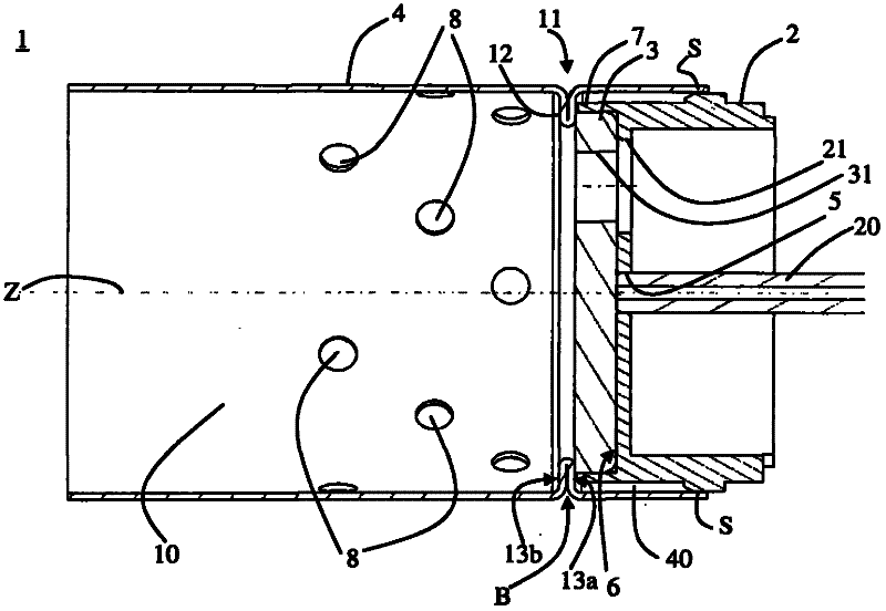
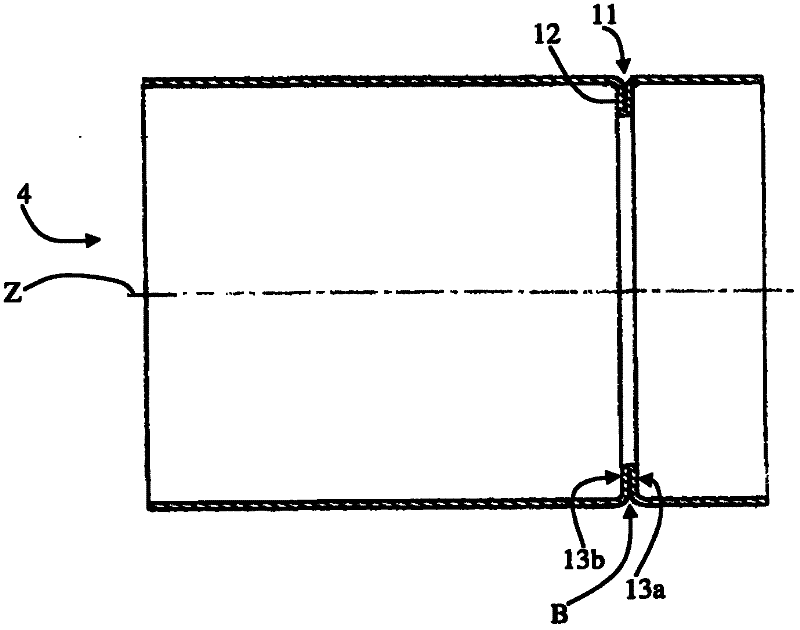
[0028] Below, refer to figure 1 with figure 2 The combustion chamber arrangement device 1 according to this embodiment is described.

[0029] In the illustrated embodiment, the combustion chamber arrangement 1 is designed for an evaporator burner of a mobile heating installation, in particular a vehicle heating installation. The vehicle heating system can be, for example, a parking heater or an auxiliary heater. In the illustrated embodiment, the combustion chamber arrangement device 1 has essentially rotational symmetry about the longitudinal axis Z, and the illustrated cross-section lies in a plane containing the longitudinal axis Z. However, it should be considered that a rotationally symmetrical design of the combustion chamber arrangement is not mandatory or necessary and that other shapes are also possible.

[0030] The combustion chamber arrangement 1 comprises an evaporator support 2 , an evaporator body 3 and a combustion chamber wall 4 . The combustion chamber a...


PUM


Abstract

The invention provides a combustion chamber configuration device for an evaporator type combustor, especially for a mobile heating device, which includes: an evaporator supporter (2) for holding an evaporator body (3), wherein a fuel supply section opening accesses to the evaporator supporter; an evaporator body (3) made of the absorptive material, wherein the evaporator body (3) is abutted against the evaporator supporter (2) and a circumferential combustion chamber wall (4) which is fixed to the evaporator supporter (2) for forming a combustion chamber (10) which converts the fuel by using the combustion air. The combustion chamber wall (4) includes an inward-extended projection (12) which is formed by deformation of the material of the combustion chamber wall (4) and the evaporator body (3) is retained in a manner that the inward-extended projection (12) abuts against the evaporator supporter (2).

Description

technical field [0001] The invention relates to a combustion chamber arrangement for evaporator burners, in particular evaporator burners for mobile heating installations. Furthermore, the invention provides a method of producing a combustion chamber arrangement for an evaporator burner. Background technique [0002] Heating devices respectively intended for mobile use or for use in mobile locations (hereinafter referred to as mobile heating devices) are used especially in the vehicle sector as parking heaters or auxiliary heaters. The parking heater (or parking heating device) is operable when the vehicle engine is stopped as well as when the vehicle engine is running. The auxiliary heater can only be operated when the vehicle engine is running. In such heating plants, generally fuel and combustion air are converted to generate heat. For this purpose, such mobile heating devices include a combustion chamber in which the transformation usually takes place by way of flame ...

Claims


Application Information

Patent Timeline
IPC IPC(8): F23D11/44
CPCF23N2041/14F23D5/123F23D3/40F23D2213/00F23N2241/14F23D3/00
Inventor M·施塔克I·瓦尔特J·斯特芬斯
Owner WEBASTO AG
Learn More