Glass substrate bonding method, glass assembly, package manufacturing method, package, piezoelectric vibrator, oscillator, electronic device, and radio-controlled timepiece

A piezoelectric vibrator and glass substrate technology, applied in the field of radio clocks, can solve the problems of increased sheet resistance of Si film, applied voltage of Si film, increased energy consumption, etc.

Inactive Publication Date: 2011-09-28
SEIKO INSTR INC
View PDF2 Cites 3 Cited by
  • Summary
  • Abstract
  • Description
  • Claims
  • Application Information

AI Technical Summary

Problems solved by technology

As a result, the potential of the bonding material becomes non-uniform, and there is a problem that anodic bonding can be performed near the probe connection point, but cannot be performed at a location far from the probe connection point.
In addition, when anodic bonding is performed at a location far from the connection point of the probe, it is necessary to apply a high voltage to perform anodic bonding, which increases energy consumption.
On the other hand, it is possible to reduce the sheet resistance by forming the Si film thicker, but in this case, the Si film formation time becomes longer, which leads to a decrease in production efficiency.
[0009] Furthermore, the Si film can be formed by the CVD method, but impurities (boron contained in the target) are scattered during the film formation, so that the impurity content in the formed Si film decreases.
As a result, the sheet resistance of the Si film further increases, and it may not be possible to directly apply a voltage to the Si film.
In addition, when forming a Si film by CVD method, special gas such as monosilane gas is used, so it is difficult to handle and difficult to introduce

Method used


Image

  • Glass substrate bonding method, glass assembly, package manufacturing method, package, piezoelectric vibrator, oscillator, electronic device, and radio-controlled timepiece
  • Glass substrate bonding method, glass assembly, package manufacturing method, package, piezoelectric vibrator, oscillator, electronic device, and radio-controlled timepiece
  • Glass substrate bonding method, glass assembly, package manufacturing method, package, piezoelectric vibrator, oscillator, electronic device, and radio-controlled timepiece

Examples


Embodiment Construction

[0054] Hereinafter, embodiments of the present invention will be described with reference to the drawings.

[0055] (Piezo Vibrator)

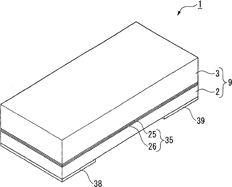
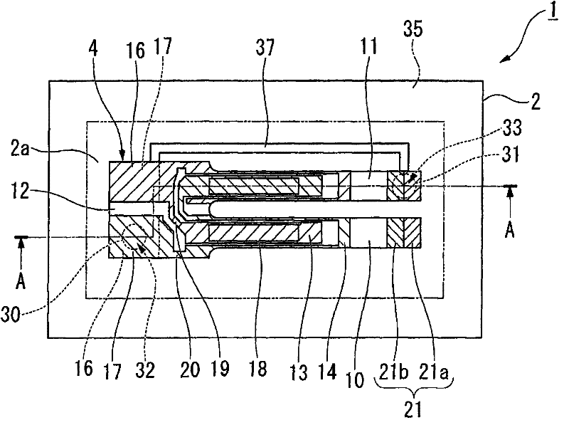
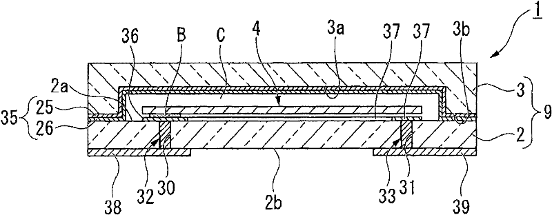
[0056] Hereinafter, a piezoelectric vibrator according to an embodiment of the present invention will be described with reference to the drawings. figure 1 It is an external perspective view of the piezoelectric vibrator according to the embodiment. figure 2 It is a plan view of the piezoelectric vibrator in a state where the cover substrate is removed. image 3 is along figure 2 A side sectional view of line A-A. Figure 4 It is an exploded perspective view of a piezoelectric vibrator. Also in Figure 4 In the drawing, the illustration of the excitation electrode 15, the lead-out electrodes 19, 20, the assembly electrodes 16, 17, and the weight metal film 21 of the piezoelectric vibrating reed 4 described later is omitted for the convenience of viewing the drawings.

[0057] like Figure 1 ~ Figure 4 As shown, the piezoelectric vibrat...


PUM


Abstract

Provided are a glass substrate bonding method capable of securely anodically bonding a bonding material and a glass substrate even when Si having a large resistance value is used as a material for the bonding material, a glass assembly obtained by the glass substrate bonding method, a package manufacturing method, a package, a piezoelectric vibrator, and an oscillator, an electronic device, and a radio-controlled timepiece having the piezoelectric vibrator. A glass substrate bonding method includes an anodic bonding step of anodically bonding a bonding material (35) fixed to an inner surface of a lid substrate wafer (50) to a base substrate wafer. The bonding material (35) is formed of an ITO film (25) and a Si film (26) which are sequentially formed on the inner surface of the lid substrate wafer (50).

Description

technical field [0001] The present invention relates to a bonding method of glass substrates, a glass bonded body, a manufacturing method of a package, a package, a piezoelectric vibrator, an oscillator, electronic equipment, and a radio clock. Background technique [0002] In recent years, piezoelectric vibrators (packages) using crystals or the like as a time source, a timing source such as a control signal, a reference signal source, and the like have been used in mobile phones and portable information terminal devices. Various such piezoelectric vibrators are known, but as one of them, a surface mount (SMD) type piezoelectric vibrator is known. Such a piezoelectric vibrator includes, for example, a base substrate and a lid substrate made of a glass material bonded to each other; a cavity formed between the two substrates; and a piezoelectric vibrator housed in a state hermetically sealed in the cavity. Vibrator (electronic component). [0003] Anodic bonding has been p...

Claims


Application Information

Patent Timeline
Patent Type & Authority Applications(China)
IPC IPC(8): H03H9/19H03H3/02H03H9/02G04G9/02H01L23/08H01L23/10H03H9/10
CPCH03H9/1021H03H9/21Y10T29/42
Inventor 沼田理志荒武洁
Owner SEIKO INSTR INC
Why Eureka
Try Eureka