Flywheel energy storage system

A flywheel energy storage and flywheel technology, applied in the field of flywheel energy storage systems, can solve problems such as low chemical energy efficiency and unsuitable motors.

Inactive Publication Date: 2011-09-28
查尔斯・吉布森 +1
View PDF5 Cites 14 Cited by
  • Summary
  • Abstract
  • Description
  • Claims
  • Application Information

AI Technical Summary

Problems solved by technology

[0003] Although advances in battery technology have made batteries more efficient, durable and capable of storing energy, the efficiency of converting mechanical energy into chemical energy stored in the battery and vice versa remains low
In addition, the motor is not suitable for use in the case of high power loads and variable power loads

Method used


Image

  • Flywheel energy storage system
  • Flywheel energy storage system
  • Flywheel energy storage system

Examples


Embodiment Construction

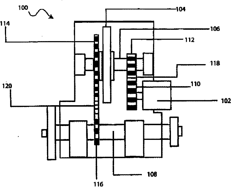
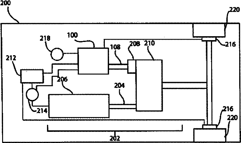
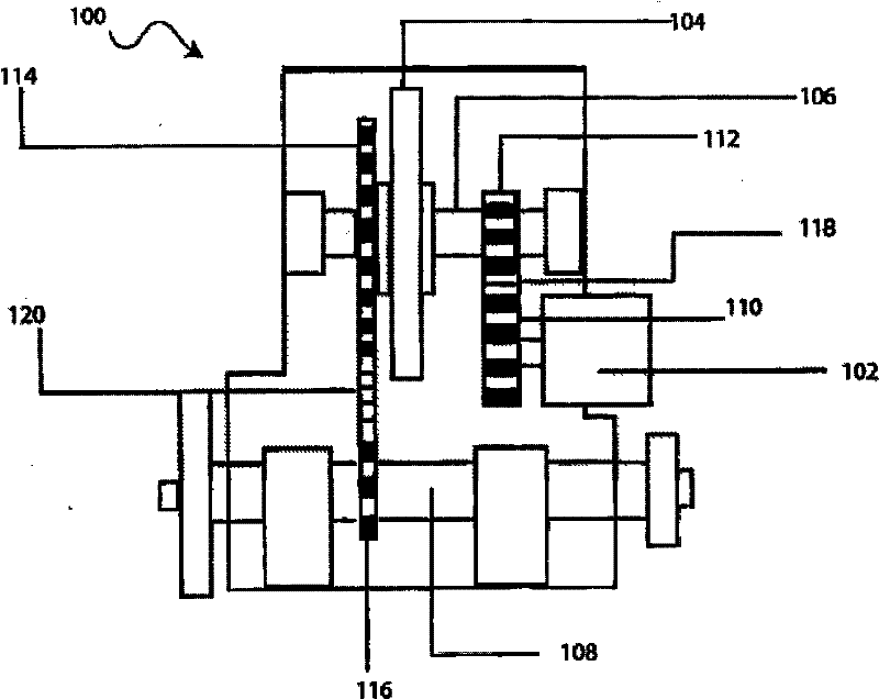
[0007] The following description of specific embodiments of the invention and the associated drawings are used to disclose various aspects of the invention. Alternative embodiments may be devised without departing from the spirit and scope of the present invention. In addition, in order to highlight the relevant details of the present invention, the well-known parts in the industry in the embodiments will not be repeated. In addition, for a better understanding of the expressions in the text, several terms are defined as follows.

[0008] "Embodiments" means "to illustrate by way of examples, specific situations or illustrations", and the implementations described herein are not limited to the examples, but are just representations. It should be understood that the illustrated embodiments are not necessarily preferred or advantageous over other embodiments. Furthermore, terms such as "embodiments of the invention", "embodiments", "the invention" and the like do not require t...


PUM


Abstract

A flywheel energy storage system for a vehicle, comprising a first shaft, a second shaft operatively coupled to the first shaft and to the vehicle's drivetrain, a flywheel operatively coupled to the first shaft, and a motor operatively coupled to the first shaft and electrically coupled to a power source, the motor being adapted to receive energy from the vehicle's electrical system and the flywheel energy storage system being adapted to transfer energy to the vehicle's drive system.

Description

Background technique [0001] Shrinking gasoline supplies and rising oil prices have spurred the development of technologies that improve the fuel efficiency of motor vehicles. This development has not only led to the advent of high-efficiency internal combustion engines, but also to hybrid vehicles, which are driven by electric motors at low speeds. The power of the electric motor comes from the battery pack. When encountering heavy loads such as rapid acceleration, high-speed driving, mountain climbing, etc. or when the battery is exhausted, the internal combustion engine assists the electric motor to work. In a motor vehicle of this type, the battery pack can be charged by the internal combustion engine, or it can be powered by methods such as regenerative braking. [0002] Another approach to vehicle technology that maximizes fuel efficiency is electric vehicles, which are powered directly by electric motors powered by a battery pack. When the battery pack is depleted, the...

Claims


Application Information

Patent Timeline
Patent Type & Authority Applications(China)
IPC IPC(8): B60K6/30B60K6/22B60L50/16B60L50/30
CPCY02T10/6282Y02T10/6204B60K6/30B60K6/105Y02T10/62Y02T10/70B60K6/10B60W10/24
Inventor 查尔斯·吉布森D·罗杰斯
Owner 查尔斯・吉布森
Why Eureka
Try Eureka