Turbocharger

A technology of turbocharger and turbine rotor, which is applied in the direction of machine/engine, gas turbine device, supporting element of blades, etc., can solve the problems of reduced turbine efficiency, enlarged clearance, and large loss, and achieve the effect of improving turbine efficiency.

Active Publication Date: 2011-09-28
IHI CORP
View PDF12 Cites 19 Cited by
  • Summary
  • Abstract
  • Description
  • Claims
  • Application Information

AI Technical Summary

Problems solved by technology

[0017] However, even when the nozzle vane has a convex shape in this way, the nozzle vane is also arranged at a position relatively close to the exhaust gas introduction wall provided on the bearing housing side, and there is no connection with the exhaust gas inlet wall provided on the turbine housing side. When the gap between the introduction walls becomes large
In this case, as described above, the loss that occurs when the exhaust gas that passes through the gap on the turbine housing side flows into the turbine rotor side is compared to the loss that occurs when the exhaust gas that passes through the gap on the bearing housing side flows into the turbine rotor. The loss is relatively larger, and the turbine efficiency in the latter case is lower than that of the former
As a result, the turbine efficiency drops

Method used


Image

  • Turbocharger
  • Turbocharger
  • Turbocharger

Examples


Embodiment Construction

[0076] Hereinafter, embodiments of the present invention will be described with reference to the drawings.

[0077] The turbocharger of this embodiment is, for example, a variable capacity turbocharger capable of adjusting the flow velocity and flow angle of the exhaust gas supplied to the turbine rotor based on the increase or decrease of the gas flow rate accompanying the increase or decrease of the engine speed of the automobile. device. In addition, in each of the following drawings, in order to make each member a size that can be recognized in the drawing, the scale is appropriately changed for each member.

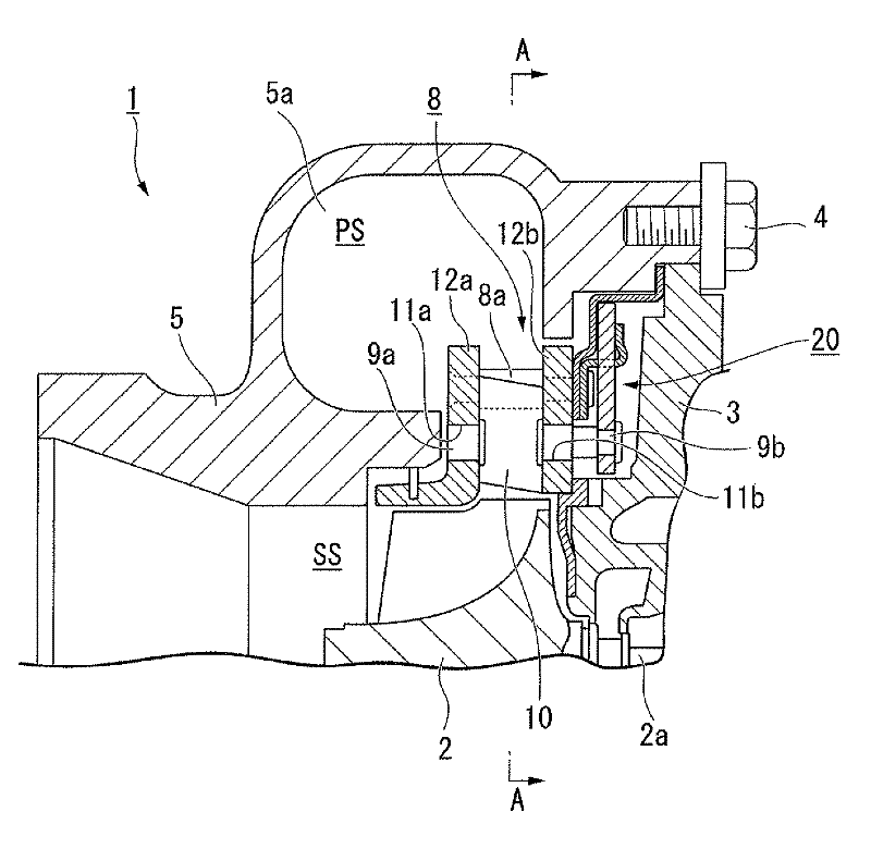
[0078] figure 1 It is a partially enlarged view of the cross-sectional view of the turbocharger of the present embodiment.

[0079] Such as figure 1 As shown, the turbocharger 1 of the present embodiment includes a bearing housing 3 that rotatably supports the turbine rotor 2 . A turbine housing 5 is integrally attached to one side of the bearing housing 3 (upper...


PUM


Abstract

A variable-geometry turbocharger comprising a bearing housing which supports a turbine impeller rotatably, a turbine housing in which a scroll channel for supplying exhaust gas to the turbine impeller is formed, and an exhaust nozzle which can change the flow velocity and flow angle of the exhaust gas to be supplied from the scroll channel to the turbine impeller side, wherein the exhaust nozzle is equipped with a pair of exhaust gas introduction walls which form an exhaust gas channel, and a plurality of nozzle vanes which are arranged between the pair of exhaust gas introduction walls and supported rotatably on the periphery of the turbine impeller, and wherein the nozzle vane has a high pressure-side wall surface facing the scroll channel and is provided in such a manner that the bearing housing side of the high pressure-side wall surface is closer to the turbine impeller than the turbine housing side, and the nozzle vane moves to the turbine housing side or pushes the exhaust gas introduction wall on the turbine housing side so that the clearance between the exhaust gas introduction wall provided on the turbine housing side, out of the pair of exhaust gas introduction walls, and the nozzle vane is narrowed when the turbine impeller is rotating.

Description

technical field [0001] The present invention relates to turbochargers. [0002] This application claims the priority of Japanese Patent Application No. 2008-284140 for which it applied in Japan on November 5, 2008, The content is used here. Background technique [0003] Conventionally, there is known a bearing housing that rotatably supports a turbine rotor, a turbine housing in which a vortex flow path for supplying exhaust gas to the turbine rotor is formed, and a flow rate of the exhaust gas supplied from the vortex flow path to the turbine rotor side. and a variable capacity turbocharger having an exhaust nozzle with a variable flow angle (for example, refer to Patent Document 1). [0004] The exhaust nozzle of the variable-capacity turbocharger of Patent Document 1 is equipped with a movable nozzle on a pair of parallel walls (exhaust gas introduction walls) between the spiral chamber (swirl flow path) and the impeller (turbine rotor). Nozzle vanes (nozzle fins). In ...

Claims


Application Information

Patent Timeline
Patent Type & Authority Applications(China)
IPC IPC(8): F02B37/24F01D17/16F02B39/00
CPCF05B2250/314F05B2250/71F05D2250/71F01D17/165F05D2250/292F01D5/141F05D2220/40F05B2220/40F05D2250/314F02B37/24F05B2250/292F02C6/12
Inventor 长尾健一森田功海野圣子小野博基
Owner IHI CORP
Why Eureka
Try Eureka