Experimental device and method for simulating influence of cracks on nano-magnetofluid oil displacement effect

A nano-magnetic fluid and simulated fracture technology, which is applied in the direction of production fluid, earthwork drilling, wellbore/well components, etc., can solve the problems of oil displacement effect fracture width, fracture density, fracture direction, etc.

Pending Publication Date: 2022-07-22
YANGTZE UNIVERSITY
View PDF1 Cites 0 Cited by
  • Summary
  • Abstract
  • Description
  • Claims
  • Application Information

AI Technical Summary

Problems solved by technology

[0003] As a new oil displacement method, nano-magnetic fluid displacement has not yet been studied on the influence of fractures on the effect of nano-magnetic fluid displacement
As we all know, the fractures in the reservoir will have a certain impact on the traditional water flooding development effect, but as a new type of displacement fluid, the relationship between the oil displacement effect of nano-magnetic fluid and the fractures in the reservoir (such as the width of the fracture, The density of fractures, the direction of fractures, etc.) are still unclear. In order to promote the application of nano-magnetic fluid flooding, it is urgent to study the influence of fractures on its oil displacement effect

Method used


Image

  • Experimental device and method for simulating influence of cracks on nano-magnetofluid oil displacement effect
  • Experimental device and method for simulating influence of cracks on nano-magnetofluid oil displacement effect
  • Experimental device and method for simulating influence of cracks on nano-magnetofluid oil displacement effect

Examples


Embodiment 1

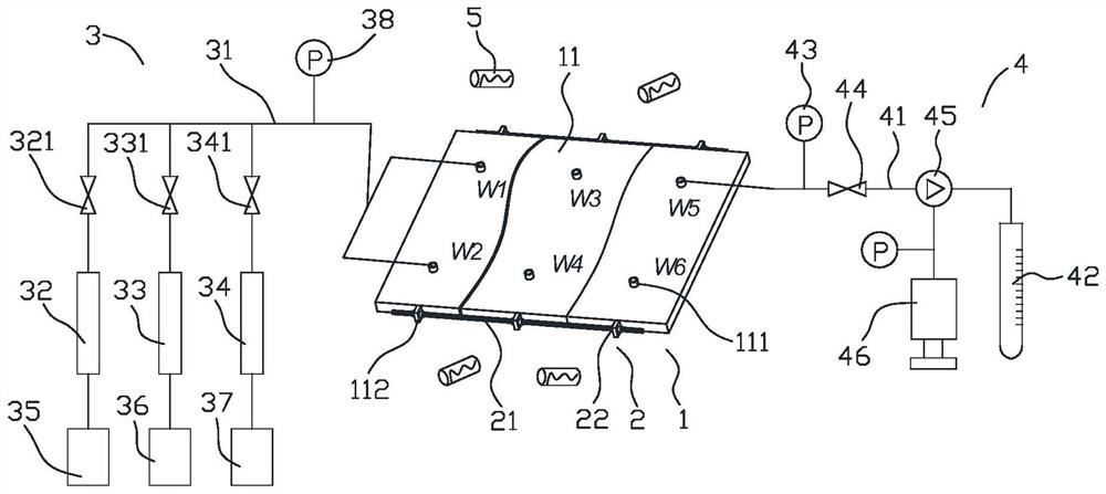
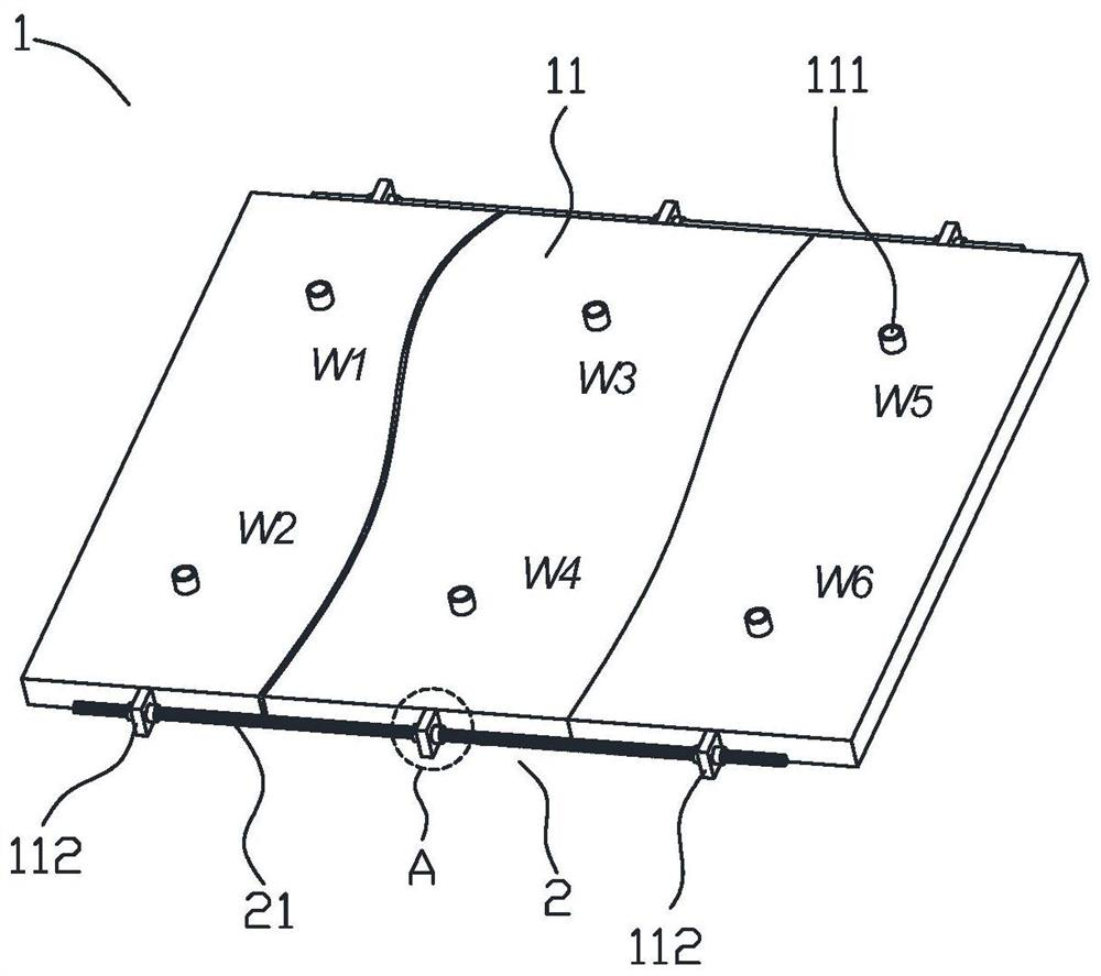
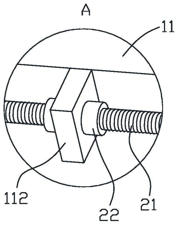
[0057] Example 1 adopts a complete rock model (ie, a rock model without fractures), the liquid injection pipe 31 is connected to the injection-production pipe numbered W1, the liquid outlet pipe 41 is connected to the injection-production pipe numbered W5, and then saturated oil is carried out according to the preceding steps. , water flooding and magnetic fluid flooding experiments.

Embodiment 2

[0059] Example 2 A rock model with two fractures was used, and the widths of the two fractures were both 1 mm. Steps to carry out saturated oil, water flooding and magnetic fluid flooding experiments. By comparing the experimental results of Example 2 and Example 1, the influence of the presence or absence of cracks on magnetic fluid displacement can be evaluated.

Embodiment 3

[0061] Example 3 A rock model containing two fractures was used, and the width of the two fractures was 2 mm. Steps to carry out saturated oil, water flooding and magnetic fluid flooding experiments. By comparing the experimental results of Example 3 and Example 2, the effect of the crack width on the magnetic fluid displacement can be evaluated.


PUM


Abstract

The invention discloses an experimental device and method for simulating the influence of cracks on the nano-magnetofluid oil displacement effect. The device comprises a rock model assembly, a clamping mechanism, a liquid injection mechanism, a liquid outlet mechanism and a magnetic field generator. The rock model assembly is composed of a plurality of model blocks formed by cutting a rock model. The clamping mechanism comprises a screw rod and a plurality of clamping nuts; the magnetic field generator is used for generating a magnetic field around the rock model assembly. The device has the beneficial effects that crude oil, water and magnetic fluid are sequentially injected into the rock model assembly through the liquid injection mechanism, the fluid is discharged from the collector after entering the rock model assembly, and a magnetic field is generated around the rock model assembly through the magnetic field generator, so that the moving direction of the magnetic fluid is controlled; the distance between the two adjacent model blocks can be adjusted through the clamping mechanism, so that the influence of the width of the crack on the oil displacement of the magnetic fluid can be simulated, and the relation between the oil displacement effect of the nano magnetic fluid and the crack in the reservoir can be simulated through the technical scheme.

Description

technical field [0001] The invention relates to the technical field of magnetic fluid displacement, in particular to an experimental device for simulating the influence of fractures on the oil displacement effect of nanometer magnetic fluid. Background technique [0002] Magnetic nanofluid is a new type of functional material, which has both the fluidity of liquid and the magnetism of solid magnetic material. The flow behavior of ferrofluid can be controlled by an external magnetic field. Because of this, it has a wide range of applications in practice, such as magnetic fluid. Sealing, lubrication, mineral processing, medical equipment, sound and light adjustment, etc. Foreign scholars have carried out experimental studies on the flow of nano-magnetic fluid in porous media (Borglin S., Moridis G., Oldenburg C. Experimental Studies of the Flow of Ferrofluid in Porous Media [J]. Transport in Porous Media, 2000, 41(1) : 61-80.), the results show that the flow direction of nano...

Claims


Application Information

Patent Timeline
IPC IPC(8): E21B43/16E21B47/00
CPCE21B43/16E21B47/00
Inventor 汪杰张良君江厚顺
Owner YANGTZE UNIVERSITY
Why Eureka
Try Eureka